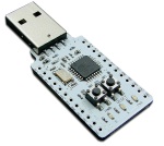
I was nicely surprised to hear from some of the Northackton chaps that there was a new, very cheap (around a fiver) board you can get that plugs directly into a PC with fully programmable I/O (input/output) connections and a free development kit. That board turned out to be a Minimus USB and I got hold of one for a play straight away.
I won’t recount all the details of it here, its all one the websites, but you can buy them for around £5 and they are basically an ATMEL microcontroller (AT90USB162), 2 LEDs, 2 switches and a USB connector – and thats about it! Here is a good article from MakeStuff introducing the board and what it can do.
This is the first in a series of posts about it and what I’ve been up to.
First a disclaimer – I am not an electronics person! I am software and networks through and through, so I make no guarantees for technical accuracy in any of this. It has been pulled together from all corners of the Internet and it all worked for me. It hasn’t fried anything yet, but that is all the assurance you’ll get.
Now like many software engineers, when faced with a bit of hardware with LEDs on it, I wanted to make them flash! Well to do that I needed a few things to get started – namely a development environment and a means to programme the device.
WinAVR gives an IDE (Programmers Notepad), ports of the GNU compilers for AVR devices and a full set of standard library definitions for AVR chips. Atmel’s own FLIP software provides a means of sending compiled binaries to the device and the minimus includes its own bootloader software all ready to go.
Other useful information:
- AT90USB162 main page (with manuals, reference guides, etc)
- Reading Hackspace Minimus Info
- Minimus schematic
So I installed it all, following the instructions, and got started on my first programme to make the LEDs flash. I started with the demo LED programme provided on the minimus USB website. This compiled up and loaded ok, but I wanted to know more about how it all worked, so I looked up the basics of driving an AVR to make its input/output ports work. I stumbled on this explanation, telling me about the main three registers and pull-up resistors and so on, which was very useful.
What I didn’t find easily was anything that say “poke this bit with a 1 or 0 to make X happen”. The sample code tends to toggle the LEDs and things, but eventually from the schematic and some experimentation I realised that the switch reads 0 when pressed and 1 otherwise (PD7 is tied to 5v in the schematic and pulled low when you press the switch) and that similarly you write a 0 to PD5 or PD6 to light the LEDs (they are connected between 5v and the PORT D pins).
So I ended up with the following main functions:
int switch_on ()
{
  if (PIND & (1<<PD7))
  {
    return 0;
  }
  else
  {
    return 1;
  }
}

void red_on()
{
  PORTD = PORTD & ~(1<<PD6);
}

void red_off()
{
  PORTD = PORTD | (1<<PD6);
}

void blue_on()
{
  PORTD = PORTD & ~(1<<PD5);
}

void blue_off()
{
  PORTD = PORTD | (1<<PD5);
}
Which illustrates the basics. The only thing missing then is something to initialise the I/O registers:
PORTD = 0b00000000;
DDRD = 0b01100000;
PORTD = 0xb0110000; // Start with them off
Which sets bits 5 and 6 as outputs (the LEDs), leading bit 7 as an input (as this is the switch).
The only other thing from the sample code is that you have to disable the watchdog (otherwise I guess it will trigger and reset/interrupt/whatever it is configured to do by default!)
MCUSR &= ~(1 << WDRF);
wdt_disable();
These all use the standard definitions for AVR microcontrollers provided by WinAVR’s io.h and wdt.h headers.
At this point, the standard Makefile that came with the LED sample application was enough to build my source file (I’d just hacked the above into the provided C file) from within Programmers Notepad and I was off. I was then able to download the resulting hex file using FLIP and I had LEDs flashing in various sequences. I also got quite a lot of practise rolling my thumb across the switches to get the device back into programming mode once I’d run my code on it. (you can “roll” a thumb quite easily across the switches to get the right sequence: reset on – other on – reset off – other off).
I was building up a list of things to look at next – getting some kind of connector on the IO pins, tying up a range of LEDs to the IO pins and also taking at look at the LUFA USB stack to see if I could get that going. But more on those next time.
Kevin.


3 thoughts on “Minimus usb (or my quest to flash some LEDs)”