computers

Emulating a Sony Stereo Remote Control

I have a few Sony stereos about the place that largely (these days) act as amplification for something or other.  One I use with a TV, using it’s AUX setting to feed in an audio input.  The only problem is that there is no way to select the AUX input from the front panel – it has to be done with a remote control. But the remote that came with it doesn’t have an option for AUX either – it has CD, tape or tuner, but no AUX.  The only way to get to the AUX setting is using the “function” button which cycles between CD, tape, tuner and AUX!

But I’ve now lost the remote (and the spare remote I was saving “just in case” and the spare, spare turns out only works with power, CD and volume, not “function”) and someone changed the mode to CD and there is no way to get it back onto AUX!  I have a few other remote controls for Sony stereos and they have various combinations of CD, tape, tuner, MD, second tape deck, and so on.  But it seems that only the power, CD and volume controls are common, so no escape there, and second hand ones online seem to be going for upwards of £10!

So I turned to an Arduino, an infrared LED and the following websites to help:

And the Arduino IRemote library from Ken Shirrif: https://github.com/Arduino-IRremote/Arduino-IRremote.

The problem is that the usual way to use an Arduino and the IRemote library is to first get it to “dump” the IR parameters for your controller by using a LED receiver and your existing remote control.  But I’ve lost mine, so no joy there.

As I say, I did have some similar remotes and wondered if sampling the selection buttons from them might lead to an obvious omission that I could infer was the AUX setting.  So using the “ReceiveDump” sample application and the following circuit I was able to grab the magic numbers from some of the remotes I still have.

Arduino IR RX_bb

WARNING: Check the pinout for the IR receiver you have, there are several different varieties! I’ve found some with the pinouts reversed to that shown above.

This gives an output over the serial link like the following:

Protocol=Sony Address=0x10 Command=0x25 Raw-Data=0x825 12 bits LSB first

Send with: IrSender.sendSony(0x10, 0x25, <numberOfRepeats>);

Raw result in internal ticks (50 us) - with leading gap
rawData[26]: 
-65535
+47,-13
+22,-13 +11,-12 +23,-13 +11,-12
+11,-13 +23,-13 +10,-13 +11,-13
+11,-12 +11,-13 +11,-13 +23
Sum: 378
Raw result in microseconds - with leading gap
rawData[26]: 
-3276750
+2350,- 650
+1100,- 650 + 550,- 600 +1150,- 650 + 550,- 600
+ 550,- 650 +1150,- 650 + 500,- 650 + 550,- 650
+ 550,- 600 + 550,- 650 + 550,- 650 +1150
Sum: 18900

Result as internal ticks (50 us) array - compensated with MARK_EXCESS_MICROS=20
uint8_t rawTicks[25] = {47,13, 22,13, 11,12, 23,13, 11,12, 11,13, 23,13, 10,13, 11,13, 11,12, 11,13, 11,13, 23}; // Protocol=Sony Address=0x10 Command=0x25 Raw-Data=0x825 12 bits LSB first

Result as microseconds array - compensated with MARK_EXCESS_MICROS=20
uint16_t rawData[25] = {2330,670, 1080,670, 530,620, 1130,670, 530,620, 530,670, 1130,670, 480,670, 530,670, 530,620, 530,670, 530,670, 1130}; // Protocol=Sony Address=0x10 Command=0x25 Raw-Data=0x825 12 bits LSB first

uint16_t address = 0x10;
uint16_t command = 0x25;
uint32_t data = 0x825;

Pronto Hex as string
char prontoData[] = "0000 006D 000D 0000 005B 0018 002B 0018 0016 0016 002D 0018 0016 0016 0016 0018 002D 0018 0014 0018 0016 0018 0016 0016 0016 0018 0016 0018 002D 06C3 ";

The most useful bits are the address and command portions.  These relate to the two values required to be passed back into the Arduino IRemote library sendSony() call to send that command back out over the IR LED (also shown in the circuit above).

Unfortunately there was no simple sequence of commands being detected for which I could infer some missing values!  Here is a selection of the values I was receiving for the various “CD”, “Tape”, “Tuner”, “MD”, “Aux”, and similar buttons on a RM-AMU179 and RM-SR5 remote:

Address Command   Raw-Data
 0x10    0x25      0x825    - CD
0x410    0x17     0x20817   - USB
 0x90    0x29      0x4829   - DAB
 0x10    0x18      0x818    - FM
 0x10    0x6E      0x86E    - Audio IN
 0x11    0x32      0x8B2    - CD
 0xD     0xF       0x68F    - Tuner
 0xE     0X74      0x774    - Deck A
 0xE     0x34      0x734    - Deck B
 0xF     0x2A      0x7AA    - MD

I can’t spot a pattern!  And looking more closely at the following site: http://www.hifi-remote.com/sony/Sony_rcvr.htm we can see that the selection options are pretty much “all over the place”.  I did have one “brute force” attempt at sending a selection of potentially useful looking candidates over in a loop:

for (int i=29; i<38; i++)
{
  IrSender.sendSony(0x10, i, 3, 12);
  delay(1000);
}

for (int i=64; i<74; i++)
{
  IrSender.sendSony(0x10, i, 3, 12);
  delay(1000);
}

for (int i=104; i<108; i++)
{
  IrSender.sendSony(0x10, i, 3, 12);
  delay(1000);
}

But all I could make it recognise were Tape (0x10, 0x23 or 35) and CD (0x10, 0x25 or 37).  So, over to “plan B”.

The Linux IR Control (LIRC) project has a really extensive list of IR codes for controllers, and I was able to work out that my stereo uses the Sony RM-SC1 remote control. I wasn’t able to find the setting for the AUX input (although with time that still might be possible), but I was able to find the magic numbers that need to be sent to enable the “function” button to allow me to cycle between CD, tape, tuner and AUX.

From: https://lirc.sourceforge.net/remotes/sony/RM-SC1 I can see that the “function” button is described as follows:

begin remote

  name  Sony_RM-SC1_2
  bits            7
  flags SPACE_ENC|CONST_LENGTH
  eps            30
  aeps          100

  header       2450   500
  one          1260   541
  zero          650   541
  post_data_bits  8
  post_data      0x9
  gap          44783
  toggle_bit_mask 0x0

      begin codes
          function                 0x4B
          eq                       0x63
      end codes

end remote

So this is a 7-bit command with an 8-bit “post data” fixed field containing the value 0x9, which means the code required to activate it is constructed as follows:

<7-bit command> <8-bit post-data fixed value>

So this is one of the 15-bit Sony values (Sony also uses 12 and 20-bit values).

0x4B . 0x09 -> 100 1011 0000 1001

The trick is working out how to turn this into values to put into the Arduino IRemote library, which requires a “command” and an “address” for the Sony protocol.  You can read more about how to interpret these values in Ken Shirrif’s post here.

The bits as listed in the LIRC database should be read as values from right to left.  There are three formats of Sony protocol (see: https://www.sbprojects.net/knowledge/ir/sirc.php):

  • 12 bits = <7 bit command> <5 bit address>
  • 15 bits = <7 bit command> <8 bit address>
  • 20 bits = <7 bit command> <8 bits extended address> < 5 bits address>

So for our 15 bit value, we need to read the last 8 bits “back to front” as an 8-bit address:

0000 1001 -> 1001 0000 = 0x90

Then the final 7 bits are the command:

100 1011 -> 110 1001 = 0x69

This means that the call into the Arduino IRemote library we need is as follows:

 IrSender.sendSony(0x90, 0x69, 3, SIRCS_15_PROTOCOL);

Note that we need to specify we’re using the 15-bit protocol.  Cross-referencing with http://www.hifi-remote.com/sony/Sony_rcvr.htm we can look up 0x90 (144) and 0x69 (105) but that is listed as “Input +/Right” so I would never have guessed to try that from my “brute force” approach!

The easiest way to “hack” this in is to take the IRemote SimpleSender example program and place this line at the start of the main loop() function, followed by an immediate return. I included a delay and flashed the LED to show it was working.

void loop() {
  IrSender.sendSony(0x90, 0x69, 3, SIRCS_15_PROTOCOL);
  delay(200);
  digitalWrite(LED_BUILTIN, HIGH);
  delay(200);
  digitalWrite(LED_BUILTIN, LOW);
  delay(2000);

  return;

  // rest of original loop() function

When used with an InfraRed diode on D2 (with a suitable current limiting resistor), this should result in sending the “function” button press every two seconds.

Arduino IR TX_bb

My IR LED has the following properties:

  • 5mm IR LED (940nm)
  • Vf = 1.2-1.4V
  • If = 100mA

But the Arduino’s limit is 40mA (max) or 20mA (ideal) for an IO pin to drive an LED directly.

  • So @40mA/5V -> 95Ω
  • @20mA/5V -> 190Ω

I used a 220Ω resistor as I had some spare, which means I’m running with a current of I = V/R = (5 – 1.2) / 220 ~ 17mA.

Just for completeness, looking back at my original trace, we can see that some of the values I detected used a 12-bit command at address 0x10, for example:

Protocol=Sony Address=0x10 Command=0x25 Raw-Data=0x825 12 bits LSB first

Mapping this onto the values from http://www.hifi-remote.com/sony/Sony_rcvr.htm, we can see that address 0x10 is a “Sony 16” device (0x10 = 16 in decimal), and that command 0x25 (37 decimal) is “CD, CD/SACD, Aux1”.  So again for completeness this maps as follows:

  • It is a 12-bit command, so has a 5-bit address and 7-bit command.
  • The “raw” value listed is 0x825 which is 1000 0010 0101, giving an address of 1 0000 (0x10 or 16), and a command of 010 0101 (0x25 or 37).
  • Looking in the LIRC data dump for the “Select CD command” we can see the following:
begin remote

  name  Sony_RM-SC1_1
  bits           12
  flags SPACE_ENC|CONST_LENGTH
  eps            30
  aeps          100

  header       2476   491
  one          1270   532
  zero          659   532
  gap          44783
  toggle_bit_mask 0x0

      begin codes
          KEY_SLEEP                0x061                     #  Was: sleep
          KEY_POWER                0xA81                     #  Was: power
          display                  0xD21
          clock_timer_select       0x461
          clock_timer_set          0xA61
          tuner_memory             0x701
          KEY_TAPE                 0xC41                     #  Was: tape
          KEY_CD                   0xA41                     #  Was: cd
          tuner-band               0xF01
          KEY_VOLUMEUP             0x481                     #  Was: vol_plus
          KEY_VOLUMEDOWN           0xC81                     #  Was: vol_minus
      end codes

end remote

KEY_CD is 0xA41 or 1010 0100 0001.  Decoding this “backwards” using the 12-bit format <7-bit command> <5-bit address> gives:

  • [ 1010 010 ][ 0 0001 ] -> [ 1000 0 ][ 010 0101 ]
  • Address = 00001 -> 10000 = 0x10 (16)
  • Command = 101 0010 -> 010 0101 = 0x25 (37)

So the following call would trigger this command (and it does):

 IrSender.sendSony(0x10, 0x25, 3);

Note that a bit length of 12 is assumed if none is specified.

So back to the original problem. I need to use “function” several times to select through CD – tape – tuner – AUX, so I ended up just letting the above code run until the AUX setting could be seen on the display, then I turned off the Arduino!

Kevin

computers · maker

Arduino Nano Every Timers and PWM

Returning to my exploration of the Arduino Nano Every, this post examines the use of timers and how they are used for pulse width modulation (PWM) applications.

For a detailed breakdown of the use of Timers (and the source for much of the information in this post, alongside the official Microchip documentation for the ATmega4809), see:

As I mentioned in my introductory article, the Arduino Nano Every works hard to be “pin compatible” with the original Arduino Nano.  One of the reasons for the odd port mapping described is down to which pins need to support PWM.  The Nano Every supports PWM on the following pins:

  • D3 – PF5
  • D5 – PB2
  • D6 – PF4
  • D9 – PB9
  • D10 – PB1

Unlike the Nano, there is no PWM possible on D11.  Part of the reason for the odd mapping to ATmega4809 ports and IO pins is that PWM is implemented using hardware timers and there are limitations on which pins can be used with the timers.

For the ATmega328 as used on the Nano, there are three timers which can be configured each to provide two outputs (OC0A/B, OC1A/B, OC2A/B). These are mapped onto the six PWM pins for an Uno or Nano.

The ATmega4809 has five timers in total, one “type A” which has three compare channels, and four “type B” timers with one channel channel each.  The Arduino environment uses these as follows:

  • TCA: 3 compare channels:
    • 0 – PWM pin 9
    • 1 – PWM pin 10
    • 2 – PWM pin 5
  • TCB0: PWM pin 6
  • TCB1: PWM pin 3, also used for tone() function
  • TCB2: Used with the servo library
  • TCB3: Used for millis(), micros(), delay()

Note that there are many more options for the ATmega4809 itself but these are not broken out in the Arduino Nano Every.

Arduino Nano Every Timer Configuration

Which output pins are connected to which timer channel is controlled by the ATmega4809’s PORTMUX registers (see chapter 15 in the datasheet).  There are six options for the three channels of TCA: they can be mapped onto pins [5:0] for each of PORTA to PORTF depending on the setting of the TCAROUTEA register.  To use all six pins requires the use of “split mode” for TCA, but only pins [2:0] of PORTB are actually broken out for the Nano Every anyway, so “non-split mode” is used which only applies to bits [2:0].  There are two options for each of the single channels of TCB0, 1, 2 and 3, a default and alternative mapping, depending on the settings of the TCBROUTEA register.  The Arduino library has TCA (“non-split” mode) mapped onto PORTB (pins 5, 9, 10); TCB0 to PF4 (pin 6); and TCB1 to PF5 (pin 3). None of the other output pins options from the ATmega4809 are routed out to physical pins on the Arduino Every.

A major limitation with the 4809’s timer setup is that there is only one prescalar setting and it is shared across all timers.  The Arduino library configures the TCA CTRLA “CLKSEL” bits to /64 in the setup_timers() function from the relevant variant.c file:

// Use DIV64 prescaler (giving 250kHz clock), enable TCA timer
TCA0.SINGLE.CTRLA = (TCA_SINGLE_CLKSEL_DIV64_gc) | (TCA_SINGLE_ENABLE_bm);

This means that TCA is running at 250kHz, for the default system clock of 16MHz.  Then in Wiring.c it sets the system TCBn timer to use the same prescalar as TCA in the CTRLA register:

/* Clock selection -> same as TCA (F_CPU/64 -- 250kHz) */
_timer->CTRLA = TCB_CLKSEL_CLKTCA_gc;

The “_timer” pointer will be set to the TCB3 due to the Nano Every having MILLIS_USE_TIMERB3 defined in the board.txt file configuration, thus placing the system timer for millis(), micros() and delay() on TCB3.

The tone() function will set up TCB1 depending on the frequency of tone required to either the TCA prescalar value (250kHz) or the system clock value (16MHz):

if(prescaler_needed){
_timer->CTRLA = TCB_CLKSEL_CLKTCA_gc;
} else {
_timer->CTRLA = TCB_CLKSEL_CLKDIV1_gc;
}

The “prescalar_needed” flag is calculated based on the requested frequency for the tone to be played.

In terms of PWM, the counters are all initialised (again in the setup_timers() function in variant.c), alongside the prescalar values, to give a base PWM frequency of 977Hz.  The timers are configured to run in 8-bit mode, with a period of 255 (via the PWM_TIMER_PERIOD define in timers.h).  In fact this is done for all timers apart from TCB3.  Incidentally this is where the routing of timers to IO pins is setup too.

Why 977Hz?  Well, 16Mhz / 64 = 250kHz as already mentioned.  With a counter (period) of 255, the counters will count from 0 to 255 at 250kHz and then reset, so 250kHz / 256 = 976.5625, so this is the default “tick” for all timers apart from TCB3.  The tone() function will mess with this for TCB1, which is why PWM on pin 3 will not be available if using tone().

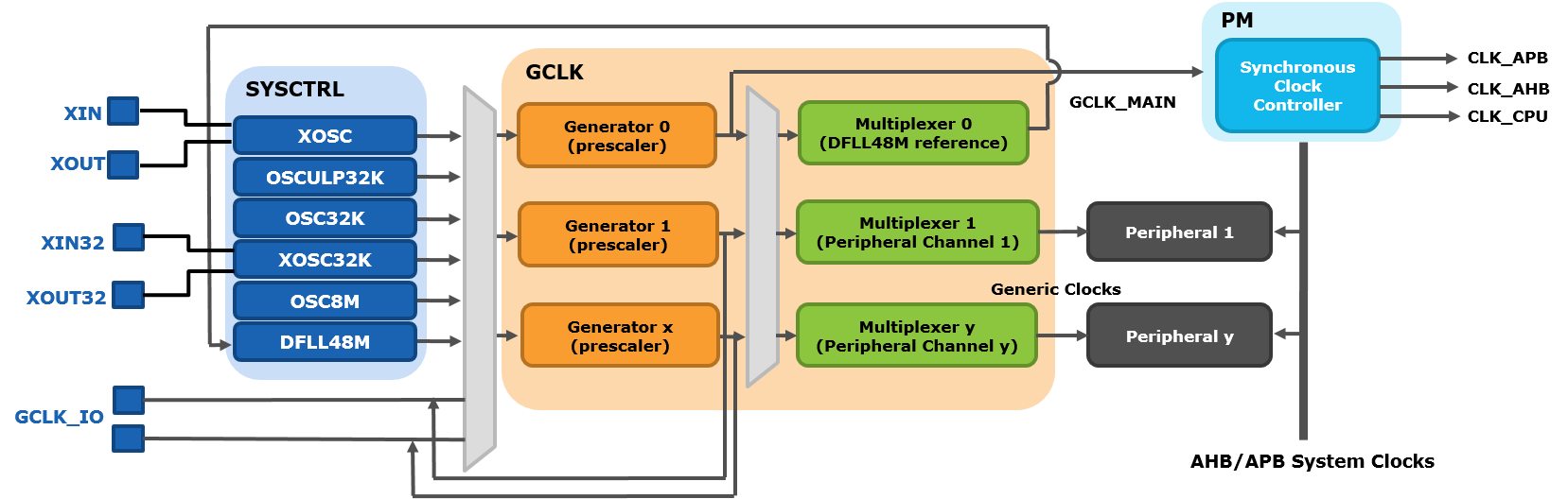
Aside: Nano Every Main Clock Configuration

For completeness, this is a brief diversion into how the main system clock is configured.  This all happens in Wiring.c which is responsible for the configuration of the timers for millis(), micros() and delay() and the implementation of these functions.

There are two main clock control registers (see chapter 10 in the ATmega4809 datasheet) that we need to worry about: MCLKCTRLA and MCLKCTRLB.  There are others, but they aren’t of interest at the moment.

MCLKCTRLA contains the main system CLKSEL configuration, which is set to 0 by default, meaning the internal 16/20 MHz oscillator, whose frequency is determined by a fuse setting (OSCCFG – see section 7.8.2.3 in the datasheet).  The assumed default of the Arduino environment is 16MHz to maintain compatibility with the original Arduino Nano (this is all configured in the board.txt file, via the .build.f_cpu and .bootloader.OSCCFG settings – Tom Almy’s book has details of how to run it at 20MHz).

MCLKCTRLB contains the configuration for the system prescalar.  In the init() function is Wiring.c it is set according to the processor speed (as specified by F_CPU).  As this is 16MHz for the Arduino environment for the Nano Every, the following code is used:

#elif (F_CPU == 16000000)
cpu_freq = 16000000;

/* No division on clock */
_PROTECTED_WRITE(CLKCTRL_MCLKCTRLB, 0x00);

This disables the pre-scalar at the system level.  The init() function eventually calls the setup_timers() function that is implemented in Variant.c (as mentioned above).

Using PWM for Audio

There are several common uses for PWM on an Arduino: controlling servos, controlling LEDs, or for audio output.  The default configuration as described above, and implemented through the analogWrite() Arduino function is fine for servos and LEDs, but not for audio.  To get anywhere near half-decent PWM audio output, there are usually two timer-related functions required:

  • Getting a hardware timer to output a voltage level using PWM in place of having an actual digital to analog converter (basically what happens with servos and LEDs, but tailored to audio frequencies).
  • Configuring a periodic timer to “play samples” by changing the PWM duty cycle value to be sent at the fixed “sample rate”.

For a detailed discussion of using PWM on an ATmega328 based Arduino, see “Secrets of Arduino PWM”.  For a detailed discussion of the use of PWM for audio, see “Open Music Labs: PWM DAC”.

Typically on an ATmega328 based system, a sample rate is chosen (e.g. 16kHz or 32kHz) that relates to the size and pitch of samples to be played (for example, from a “wavetable” at a specific frequency).  Also, for the actual PWM output itself, a core PWM frequency is required that is ideally above human hearing, so again something like 32kHz is ideal.

So, we need to configure a timer, with a PWM pin, able to run at the appropriate PWM base frequency, but with a PWM mode that allows a duty cycle to be configurable from a timer-driven interrupt routine itself running at a fixed playback rate.

If we choose the type A timer, that would give us a choice of three potential pins for output.  But it also means that other PWM applications on those pins are not possible as they are all driven from the same timer. However type B timers only have a single 8-bit PWM mode.

Timer B for Audio PWM

In terms of a fixed PWM base frequency, the default is too slow – 977Hz will just not do it.  So, the only option that doesn’t involve messing with the system clock is to override the CLKSEL mode for one of the TCB timers and set it to the system clock or the system clock / 2.  This means it will run at either 16MHz or 8MHz rather than 250kHz.  So then it is a question of setting up the compare registers to keep the PWM ticking over at a sensible speed.  The default mode (again) is as an 8-bit timer, so for it to count the full range of 0 to 255 means the PWM frequency will either be 16MHz/256 = 62.5kHz or 8MHz/256 = 31.25kHz.

Either is fine as the starting point, but exactly how many times the “PWM” triggers will normally depend on the counter’s mode.  Recall that an ATmega328 has several modes that support a PWM output.  However, whilst the ATmega4809 type A timer has several PWM modes, a type B timer, has just one PWM mode – “8-bit PWM Mode” (see section 21.3.3.1.8 in the datasheet).

In 8-bit PWM mode the 16-bit compare register is treated as two 8-bit compare registers – CCMPH and CCMPL.  The least-significant 8-bits (CCMPL) determines the period for the PWM cycle.  The most-significant 8-bits (CCMPH) determines the duty cycle.  From the datasheet:

“The period (T) is controlled by CCMPL, while CCMPH controls the duty cycle of the waveform.  The counter will conitnuously count from BOTTOM to CCMPL, and the output will be set at BOTTOM and cleared when the counter reaches CCMPH.”

So by way of example, to configure Timer B1 (the one “reserved” for the arduino tone() function) for a base frequency PWM on pin D3, we have to do the following.

PORTMUX.TCBROUTEA |= PORTMUX_TCB1_bm; // Enable "alternative" pin output (PF5=D3) for TCB1
TCB1.CTRLA = TCB_CLKSEL_CLKDIV1_gc | TCB_ENABLE_bm; // SysClk and enabled
TCB1.CTRLB = TCB_CNTMODE_PWM8_gc | TCB_CCMPEN_bm; // 8-bit PWM and output enabled
TCB1.CCMPL = 255; // Default value TOP=255, duty cycle = 25%
TCB1.CCMPH = 64;

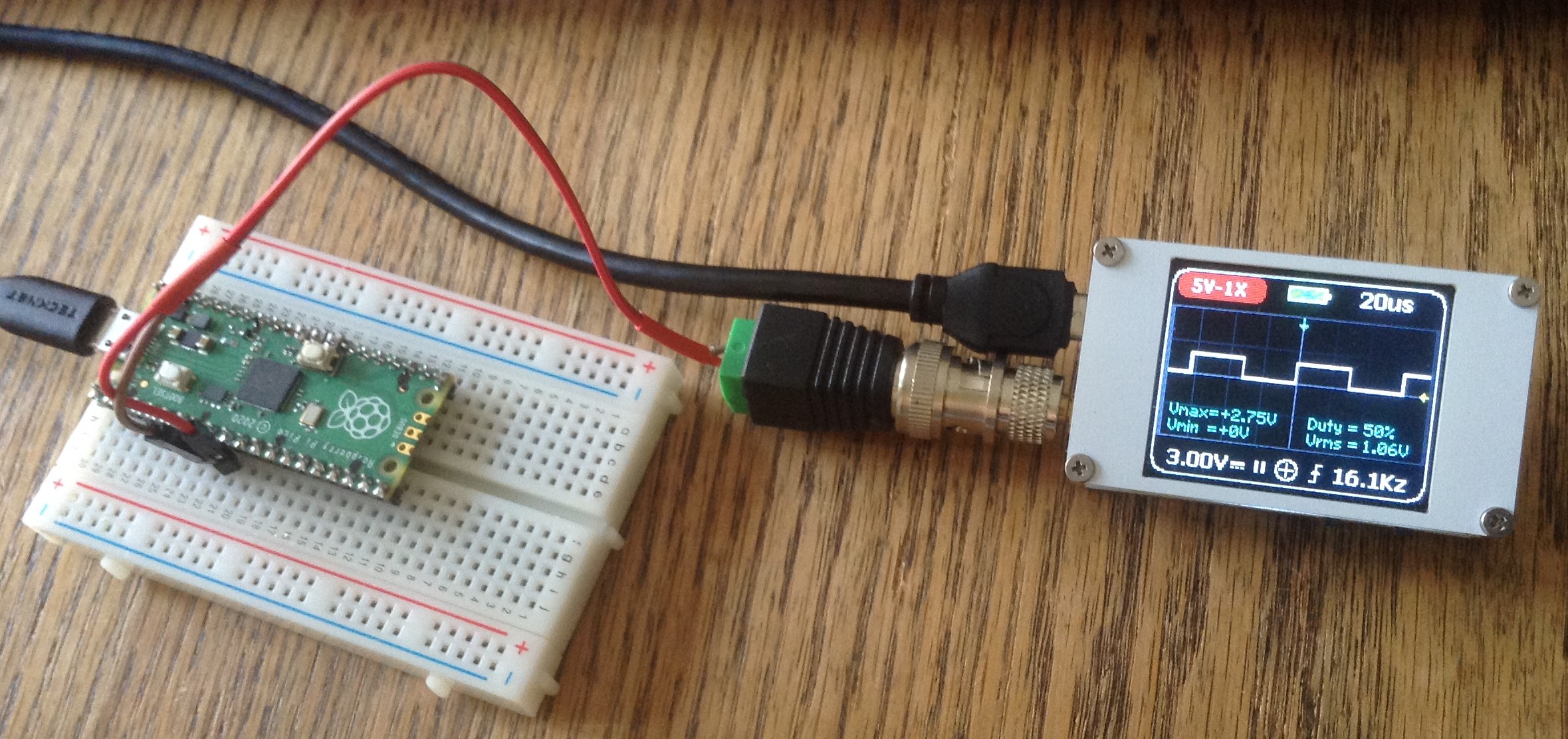
This outputs a nice 25% PWM (64 is 25% of 256) signal with a base frequency of 62.5kHz which you can see if you hook up a scope or logic analyser to D3.

So what about a timer routine to feed the PWM hardware some actual sample values?  Well the simplest option would be to hang an interrupt off the same timer to trigger on each period.

On an ATmega328 we usually have several options: interrupt on overflow (i.e. counter wrap around), interrupt on compare match, and others.  Unfortunately there is only one interrupt on a type B timer on the ATmega4809, the “capture event interrupt”.  The datasheet says it will trigger “when the counter reaches CCML” in 8-bit PWM mode, which means it triggers on every wrap-around of the counter.  So that still gives us the possibility of a 62.5kHz “tick”, so that should do the trick.

TCB1.INTCTRL |= TCB_CAPT_bm;

ISR(TCB1_INT_vect) {
// Should run at the same period as the PWM base frequency
TCB1.INTFLAGS = TCB_CAPT_bm; // Clear the interrupt flag

// Process the sample...
TCB1.CCMPL = TOP;
TCB1.CCMPH = NEW_SAMPLE; // In range 0 to TOP
}

For some reason, if I only wrote to CCMPH then it seemed to mess with the CCMPL value too, so I’ve found it best to update both in the interrupt routine.

One final note.  I won’t go into the details here, but in general terms, it makes things a lot easier (when using an 8-bit microcontroller anyway) to have your sample rate a multiple that makes calculation easier.  So for a typical wave-table synthesis application, where you might have 256 samples in your table you need to output in each period for your note, then if you choose a sample rate that is a multiple of 256, some optimisations are possible that means that you don’t need to get into floating point arithmetic or weird fractions of updates for your index into your table.

That is certainly possible here too.  We know what with our default TOP = 255 value, we can get a sample rate of 62.5kHz.  So what would it take to make it the more calculating friendly 65536 Hz?  Well we know the PWM frequency is given by (21.3.3.1.8 in the data sheet: “CCMPL+1 is the period of the output pulse”):

PWM Frequency = System Clock / (TOP value + 1)

So we can also say that:

TOP value + 1 = System Clock / PWM Frequency

So substituting for 65536 Hz and a 16MHz system clock gives us:

TOP value + 1 = 16 MHz / 65536 = 244.14

So choosing a TOP value of 243 should give us our required 65536 Hz sample rate.  The only complication now is that our samples have to be scaled to fit in a 0 to 243 range rather than a more typical 0 to 255 range.  This can be done in two ways – either simply divide by 2 if performance is critical, giving each sample a 0 to 127 value; or multiply the same by 244/256 which may involve floating or fixed point arithmetic if you don’t want to lose accuracy (although divide by 256 is the same as shift right by 8 places).

So before I finish, how does using 65536Hz help?  Well in a typical direct digital synthesis application, using a 256 byte wavetable, we need to maintain an “accumulator” to work out which sample to play from the wavetable at any one time.  If the index moves on 1 step at a time, then we know that frequency of the sounding note will be:

Frequency = Sample Rate / 256 = 256 Hz

And we also know that skipping a number (so the step is 2) will double the frequency, and “playing” each sample twice will half the frequency.  In general, it can be shown that the index into the wavetable is determined using the following:

Increment = frequency * 256 / Sample Rate

But to keep accuracy, the increment is often calculated using “fixed point arithmetic”.  This basically means, keeping it 256 times bigger than it needs to be, then diving by 256 when it is time to add it on to the accumulator.  So the actual (256 times bigger) increment is now:

Incrementx256 = frequency * 256 * 256 / Sample Rate

You can perhaps now see why having a sample rate that is a power of two is advantageous!  To calculate the index to use, the simplest way to divide by 256 is to shift right by 8 bits as follows:

Increment = Increment256 >> 8

Timer A for Audio PWM

The ATmega4809 type A timer has more useful options for audio PWM but there is a caveat.  It is also used to define the Arduino’s system “tick” which drives the functions: millis(), delay(), micros(). Messing with this timer will change the functionality of these timer-related functions too as well as any libraries that use them.

So is this an issue?  Yes for audio PWM.

The Arduino system clock runs at 16MHz (it could go up to 20MHz with the ATmega4809, but the Arduino environment keeps it at 16MHz for backwards compatibility) and the system “tick” is configured to use TCA with a prescalar setting of /64 giving a PWM frequency of 977Hz (as described previously) which is nowhere near fast enough for an audio PWM output.

Options:

  • Change the Arduino core to give more clock resolution: Tom Almy has a chapter on “Better Timer Setup” in his book “Far Inside the Arduino: Nano Every Supplement”.
  • Use a different Arduino core: MegaCoreX has an option to set the PWM frequency for example.
  • Change the “master configuration” for Timer A to be more audio friendly.
  • There might be an alternative master clock configuration, maybe involving different external crystals or something… I’ve not looked into it…
  • Go back to using the type B timers!

I’m attempting to keep to solutions that don’t involve changing the Arduino core, but the price is that I end up changing the core’s functionality, so I’m going to describe how to reconfigure TCA for use with audio and talk through the implications.

Much of the previous discussion for type B timers applies here too.  However there are now several different PWM modes that we get to choose from:

  • “Single-slope” PWM, with overflow triggered at the BOTTOM of the timer count.
  • “Dual-slope” PWM, with overflow triggered at TOP.
  • “Dual-slope” PWM, with overflow triggered at TOP and BOTTOM.
  • “Dual-slope” PWM, with overflow triggered at BOTTOM.

All PWM modes are configured using the PER (period) register and there are three compare registers that can be used: CMP0, CMP1, CMP2. These map onto the three output pins for the port as specified by TCBROUTEA – which is PORTB by default for the Nano Every.

There is also a “split mode” operation which turns the timer into two 8-bit timers, each with their own three CMPn registers and each able to drive three output waveforms on output pins, so TCA0 could in principle drive 6 PWM pins.  Split mode is only possible with Single-slope PWM.  But the Arduino Nano Every only has three output pins broken out, so there are no advantages to split mode in this case.

Starting with dual-slope operation, the period calculation is as follows.

The frequency for dual-slope operation is given by (20.3.3.4.4):

freq = Sys Clock / (2 . Prescalar . PER)

So for a PWM frequency of 32768Hz and a prescalar of 1:

PER = Sys Clock / (2 x freq) = 16MHz / (2 x 32768) = 244

So for an 8-bit PWM value of 0..255 then the calculation referred to above is required to scale it to a value in the range 0..243.

Consequently, I initialise the TCA0 timer for use with audio as follows.

pinMode(9, OUTPUT);

PORTMUX.TCAROUTEA = PORTMUX_TCA0_PORTB_gc; // Enable "alternative" pin output PORTB[5:0] for TCA0
TCA0.SINGLE.CTRLA = TCA_SINGLE_CLKSEL_DIV1_gc | TCA_SINGLE_ENABLE_bm; // SysClk and enabled
TCA0.SINGLE.CTRLB = TCA_SINGLE_CMP0EN_bm | TCA_SINGLE_WGMODE_DSTOP_gc;
TCA0.SINGLE.CTRLD = 0; // Normal (Single) mode (not split)
TCA0.SINGLE.PER = 244; // 32768 Hz "tick"
TCA0.SINGLE.CMP0 = 61; // 25% duty cycle

TCA0.SINGLE.INTCTRL |= TCA_SINGLE_OVF_bm; // Turn on interrupts

ISR(TCA0_OVF_vect) {
TCA0.SINGLE.INTFLAGS = TCA_SINGLE_OVF_bm; // Clear the interrupt flag
TCA0.SINGLE.CMP0BUF = pwmval; // Write out the PWM value (0 to 243)
}

This configures TCA0 for use with PORTB (which should already be the default anyway); sets the prescalar to 1, so TCA0 runs as system clock speed (16MHz); configures dual-slope PWM mode with overflow at TOP running at 32768Hz; and enables the CMP0 output for PB0 (D9).

Notes on the code:

  • TCA0 is now running 64 times faster than the default, so millis(), delay(), micros() will all be running 64 times faster than before!
  • The overflow interrupt routine has to clear the OVF interrupt in code.
  • The pwmval will need scaling to 0..243 as described above.
  • The PWM frequency (32768Hz) is also the sample update rate for the PWM output.
  • Only CMP0 is being used, given a PWM audio output on PB0 which is mapped to Arduino D9.
  • The PWM output is set using the CMP0 register buffer.  This means it will only actually update when the counter reaches BOTTOM.  This prevents out of phase updates.
  • Don’t forget to set D9 as an OUTPUT pin! I’ve forgotten to do this several times and it always takes a while to work out why I’m getting no PWM output!

Here is the corresponding configuration for single-slope operation:

The frequency for single-slope operation is given by (20.3.3.4.3):

freq = Sys Clock / (Prescalar . (PER + 1))

So for a PWM frequency of 32768Hz and a prescalar of 1:

PER + 1 = Sys Clock / freq = 16MHz / 32768 = 488

PER = 488 – 1 = 487

So for an 8-bit PWM value of 0..255 then the calculation referred to above is required to scale it to a value in the range 0..487.  But it could be used “as is” but it will just generate a slightly quieter signal if it isn’t using the full PWM resolution.

For this operation, I initialise the TCA0 timer for use with audio as follows.

pinMode(9, OUTPUT);

PORTMUX.TCAROUTEA = PORTMUX_TCA0_PORTB_gc; // Enable "alternative" pin output PORTB[5:0] for TCA0
TCA0.SINGLE.CTRLA = TCA_SINGLE_CLKSEL_DIV1_gc | TCA_SINGLE_ENABLE_bm; // SysClk and enabled
TCA0.SINGLE.CTRLB = TCA_SINGLE_CMP0EN_bm | TCA_SINGLE_WGMODE_SINGLESLOPE_gc;
TCA0.SINGLE.CTRLD = 0; // Normal (Single) mode (not split)
TCA0.SINGLE.PER = 487; // 32768 Hz "tick"
TCA0.SINGLE.CMP0 = 122; // 25% duty cycle

TCA0.SINGLE.INTCTRL |= TCA_SINGLE_OVF_bm; // Turn on interrupts

ISR(TCA0_OVF_vect) {
TCA0.SINGLE.INTFLAGS = TCA_SINGLE_OVF_bm; // Clear the interrupt flag
TCA0.SINGLE.CMP0BUF = pwmval; // Write out the PWM value (0 to 487)
}

This configures TCA0 for use with PORTB; sets the prescalar to 1, so TCA0 runs as system clock speed (16MHz); configures single-slope PWM mode running at 32768Hz; and enables the CMP0 output for PB0 (D9).

All the same notes from above apply but naturally the PWM value now can be in the range 0..487 if we want to utilise the full range available.

Single vs Dual-slope Operation:

  • Single: allows full 8-bit (“almost 9-bit”) PWM resolution.  Dual: requires scaling down to 0-243.
  • Dual: gives a “phase correct” update. Single: may get anomalies when updating.

So single gives more PWM resolution but at the cost of loss of phase accuracy.  This probably isn’t a major issue for audio applications (is it? I don’t know!?  Let me know :)).

Conclusion

It turns out that once the basic details have been worked through, it isn’t so bad creating audio-friendly PWM on an Arduino Nano Every.  The choice of output pin is not as straight forward as for the original Nano.  The option that has the least number of side effects and limitations (in terms of limited how other pins can be used) is to use one of the type B timers.

But TCB3 is used for the system timer, and TCB2 is used for the servo library.  These also don’t have output pins available on the board, so I opted to use TCB1 as used with the tone() function.  The thinking being that if you are using PWM audio, you probably aren’t interested in the tone() function anymore!  But this means the audio output is limited to D3.  The principles described here should apply equally well to TCB0 which would also give audio output on D6.

Using TCA0 opens up the use of D5, D9 and D10 for PWM audio output, but will interfere with the system clock and require adjustments to any use of millis(), delay() or micros().

If you have an alternative ATmega4809 microcontroller board then there are almost certainly more options in which case it would be worth investigating the unofficial MegaCoreX support, but pretty much all the theory described in this post will still apply.

At some point I’d like to investigate it myself too.

Kevin


computers · maker

Arduino Nano Every I2C and SPI Displays

In this part of my series on the Arduino Nano Every, I take a look at a couple of common displays to see how they work with the Nano Every.  In short – pretty well.  Read on for how I hooked up I2C OLED and an SPI TFT displays.

I’m using the standard Arduino environment as described in my introduction to the Nano Every.

I2C OLED Displays

I thought I’d try an OLED display first.  There are some very common ones using the SSD1306 as the interface chip that hook up to the I2C bus.  The Nano Every maintains the original Nano’s I2C pins:

  • A4 = SDA
  • A5 = SCL

You have to watch out when wiring up your OLED display as there are a number of different combinations of pinout!  In my own collection I have displays with different arrangements for VCC and GND for example.

Nano Every OLED_bb

The basic circuit is as shown on the left.  It needs just four connections: VCC (5V), GND, SCL (A5), SDA (A4).  Also above you can see how you could wire it up for two displays, but one of them will need to have the I2C address changed, before you can do this, but more on that in a moment.

I’m using the Adafruit graphics library for the SSD1306 range of displays.  The default is to use hardware I2C so all that is required is to set the I2C address to match the display you have.  My displays come with a default address of 0x3C (although it is marked as 0x78 on the actual display if it is marked at all – the this is due to the least significant bit not be part of the address itself, but it is often included – so 0x3C is the address, but “on the wire” it has to be shifted one bit to the left, which then “looks” like 0x78… but anyway…).

I’ve grabbed the example from: Examples -> SSD1306 -> ssd1306128x64_i2c.  The line that sets the address is the following one:

#define SCREEN_ADDRESS 0x3C ///< See datasheet for Address; 0x3D for 128x64, 0x3C for 128x32

The datasheet referred to is for Adafruit’s own displays where the 128×64 is on 0x3D and the 128×32 is on 0x3C.  For most other displays the default is probably like mine – 0x3C.

I’ve attempted to run two displays before, but an Arduino Uno or Nano just doesn’t have enough memory to support two complete frame buffers for two 128×64 displays.  I’ve managed to configure them as 128×32 displays and got two of them running, but that is all.  So I was keen to try with the Nano Every as it has more memory!

Some displays have a jumper on the back to let you change the address, but on mine they are a fiddly surface mount resistor which needs desoldering from one link and moving to another.  Some displays aren’t configurable at all. I have some of both, as shown below.

IMG_5624

You can perhaps spot how my dodgy soldering has just about managed to move the jumper from the 0x78 position to the 0x7A position! Mind you, it took a couple of goes!

In terms of showing it working, I replicated a couple of lines of the Adafruit demo code to get as far as showing the logo on the second screen.  I didn’t change anything else.  At the top of the file, the following lines need to be added.

#define SCREEN2_ADDRESS 0x3D ///< See datasheet for Address; 0x3D for 128x64, 0x3C for 128x32
Adafruit_SSD1306 display2(SCREEN_WIDTH, SCREEN_HEIGHT, &Wire, OLED_RESET);

Then in the setup() code, I added the following.

if(!display2.begin(SSD1306_SWITCHCAPVCC, SCREEN2_ADDRESS)) {
Serial.println(F("SSD1306 allocation failed"));
} else {
display2.display();
}

This means that if a second display (on address 0x3D) is found then it will show the initial logo and then nothing else for that display, whilst the code goes on the run through the full demo on the other display (on address 0x3C).

IMG_5623

ST7735 SPI TFT Display

Next I turned to the cheap TFT displays I’ve looked at before.

Note the display in the Fritzing diagram below is just for illustration as I don’t have an exact match (the observant among you might notice I have one extra pin on mine!). Be sure to check and double check the required pins and expected voltage level for your display module.

Nano Every TFT_bb

One of the differences between the Nano Every and the original Nano is that the SPI SS pin is on pin 8, not pin 10. This means the required pin connections for my display are as follows:

 1-VCC - 5V
2-GND - GND
3-N/C
4-N/C
5-N/C
6-N/C
7-CLK - 13 (SCLK)
8-SDA - 11 (MOSI)
9-RS - 10 (D10)
10-RST - 9 (D9)
11-CS - 8 (D8)

I’m using the Adafruit ST7735 library this time.  Taking the code from:

Examples -> Adafruit ST7735 and ST7739 Library -> graphicstest

the pins must be configured at the top as follows:

#define TFT_CS   8
#define TFT_RST 9
#define TFT_DC 10

Then all the graphics primitives from the Adafruit GFX Library should be available.

IMG_5627

Conclusion

I was anticipating some issues with the displays, but actually they worked pretty well.  Most of this is down to the fact that the Wire (I2C) and SPI Libraries are part of the “built-in” library support provided by the Arduino environment and the low-level drivers for the displays provided by Adafruit are written well with minimal reliance on hardware specific features of any single microcontroller.

Kevin


computers · maker

Arduino Nano Every Analog Inputs

The next part in my series on the Arduino Nano Every, looks at how to access the additional 6 analog inputs that can be found scattered around the digital IO pins.

As I mentioned in my introductory article, the Arduino Nano Every works hard to be “pin compatible” with the original Arduino Nano.  This means that it supports 8 analog inputs, labelled A0 to A7, all along one side of the board.  But the ATmega4809 actually has 18 analog inputs, and the additional ones can be found as extra functions on some of the other pins.  Reading the data sheet, we can see that the 16 analog inputs are mapped as follows (I’ve included the Arduino pin numbers for reference):

  • AIN0 -> PD0 – A3
  • AIN1 -> PD1 – A2
  • AIN2 -> PD2 – A1
  • AIN3 -> PD3 – A0
  • AIN4 -> PD4 – A6
  • AIN5 -> PD5 – A7
  • AIN6 -> PD6
  • AIN7 -> PD7 – AREF
  • AIN8 -> PE0 – D11
  • AIN9 -> PE1 – D12
  • AIN10 -> PE2 – D13
  • AIN11 -> PE3 – D8
  • AIN12 -> PF2 – A4
  • AIN13 -> PF3 – A5
  • AIN14 -> PF4 – D6
  • AIN15 -> PF5 – D3

Note that AIN6 (PD6) is not connected and that AIN7 (PD7) is used for AREF.

To allow the Arduino environment to support the extra analog inputs, there are a few lists and structures in the Arduino “pins” definition file for the Nano Every (the same place that we tweaked to add serial ports last time):

...../arduino15/packages/arduino/hardware/megaavr/1.8.5/variants/nona4809/pins_arduino.h

There are several entries in this file that determine the mapping of Arduino pin labels to MCU ports and pins.  However there is a slight issue.  The pins for A0 to A7 are contiguous in the Arduino’s pin mappings – they map onto (internal) pins 14-21.  This means that you can do things like the following quite happily and it will all work:

for (int i=0; i<8; i++) {
aval[i] = analogRead(A0+i);
}

So to extend the range of analog inputs to include A8 to A13, ideally we’d extend the original range so that “A0+8 = A8” but these (internal) pin numbers are already taken for other functions (in this case the I2C and USB serial connections).  One option is to “shuffle” these other functions down to make room.  The other is to accept that “A7+1 != A8” and leave a gap. In what follows I’ve opted to leave a gap…

So here are the changes we need to make to pins_arduino.h.

There is a definition of NUM_ANALOG_INPUTS that isn’t really the number of analog inputs, but is used to determined the “highest numbered analog channel” used.  This is currently set to 14, but needs updating to 16.

#define NUM_ANALOG_INPUTS 16

We now need to set up some new pin definitions (e.g. PIN_A8 and A8 onwards) as follows. This is where the “gap” first becomes apparent as “internal” pin numbers 22 to 25 are already in use.

#define PIN_A0 (14) // AIN3
#define PIN_A1 (15) // AIN2
#define PIN_A2 (16) // AIN1
#define PIN_A3 (17) // AIN0
#define PIN_A4 (18) // PF2 / AIN12
#define PIN_A5 (19) // PF3 / AIN13
#define PIN_A6 (20) // AIN5
#define PIN_A7 (21) // AIN4

// Additional analog inputs
// Arduino pin numbering starts after OFFICIAL pin
// numbers end...
// Note: AIN6/AIN7 don't make it to Arduino pins
#define ANALOG_INPUT_EXTRA 26
#define PIN_A8 (ANALOG_INPUT_EXTRA) // AIN8
#define PIN_A9 (ANALOG_INPUT_EXTRA+1) // AIN9
#define PIN_A10 (ANALOG_INPUT_EXTRA+2) // AIN10
#define PIN_A11 (ANALOG_INPUT_EXTRA+3) // AIN11
#define PIN_A12 (ANALOG_INPUT_EXTRA+4) // AIN14
#define PIN_A13 (ANALOG_INPUT_EXTRA+5) // AIN15

static const uint8_t A0 = PIN_A0;
static const uint8_t A1 = PIN_A1;
static const uint8_t A2 = PIN_A2;
static const uint8_t A3 = PIN_A3;
static const uint8_t A4 = PIN_A4;
static const uint8_t A5 = PIN_A5;
static const uint8_t A6 = PIN_A6;
static const uint8_t A7 = PIN_A7;
static const uint8_t A8 = PIN_A8;
static const uint8_t A9 = PIN_A9;
static const uint8_t A10 = PIN_A10;
static const uint8_t A11 = PIN_A11;
static const uint8_t A12 = PIN_A12;
static const uint8_t A13 = PIN_A13;

Then there are four structures that map these internal pin numbers onto various properties of the hardware.  Each of these needs our additional six new entries adding in at the end.

const uint8_t digital_pin_to_port[] = {
... skip "internal" pins 0 through to 25 ...
PE, // 26 PE0/AI8
PE, // 27 PE1/AI9
PE, // 28 PE2/AI10
PE, // 29 PE3/AI11
PF, // 30 PF4/AI14
PF, // 31 PF5/AI15
};

const uint8_t digital_pin_to_bit_position[] = {
... skip "internal" pins 0 through to 25 ...
PIN0_bp, // 26 PE0/AI8
PIN1_bp, // 27 PE1/AI9
PIN2_bp, // 28 PE2/AI10
PIN3_bp, // 29 PE3/AI11
PIN4_bp, // 30 PF4/AI14
PIN5_bp, // 31 PF5/AI15
};

const uint8_t digital_pin_to_bit_mask[] = {
... skip "internal" pins 0 through to 25 ...
PIN0_bm, // 26 PE0/AI8
PIN1_bm, // 27 PE1/AI9
PIN2_bm, // 28 PE2/AI10
PIN3_bm, // 29 PE3/AI11
PIN4_bm, // 30 PF4/AI14
PIN5_bm, // 31 PF5/AI15
};

const uint8_t digital_pin_to_timer[] = {
... skip "internal" pins 0 through to 25 ...
NOT_ON_TIMER, // 26 PE0/AI8
NOT_ON_TIMER, // 27 PE1/AI9
NOT_ON_TIMER, // 28 PE2/AI10
NOT_ON_TIMER, // 29 PE3/AI11
NOT_ON_TIMER, // 30 PF4/AI14
NOT_ON_TIMER, // 31 PF5/AI15
};

Finally there is a macro that is used to spot if the analogRead function has been given a “An” label or a “Dn” number and maps that onto the appropriate analog input channel on the chip.  That needs to be updated in two ways:

  • The extra six analog inputs need the appropriate analog channels (AINxx) defining and adding.
  • The “translation” macro, digitalPinToAnalogInput(p), needs to take into account the gap in the analog input range.
const uint8_t analog_pin_to_channel[] = {
3,
2,
1,
0,
12,
13,
4,
5,
// Start of extra analog inputs
8,
9,
10,
11,
14,
15
};

#endif

#define digitalPinToAnalogInput(p) ((p < ANALOG_INPUT_OFFSET) ? analog_pin_to_channel[p] : \
(p < ANALOG_INPUT_EXTRA) ? (analog_pin_to_channel[p - ANALOG_INPUT_OFFSET] ) : (analog_pin_to_channel[p - ANALOG_INPUT_EXTRA + 8] ) )

The digitalPinToAnalogInput macro basically says:

  • IF provided pin is in digital range, just use the pin number directly as the index into the analog_pin_to_channel array.
  • ELSE IF provided pin is in the original A0 to A7 range, then subtract the number for A0, then use as an index into the analog_pin_to_channel array.
  • ELSE provided pin is in the new extended range, so subtract the number for A8 and add 8, and use that as the index into the analog_pin_to_channel array.

In all cases we should end up reading out which AINxx channel to use from the analog_pin_to_channel array and it will work for all the following input ranges:

  • 0 to 13 – analog inputs A0 to A13.
  • A0 (14) to A7 (21) – analog inputs A0 to A7.
  • A8 (26) to A13 (31) – analog inputs A8 to A13.

With those changes, A0 through to A13 should now all be usable, although remember that A8 does not directly follow (numerically) A7.

Here is some test code to read all 14 analog inputs.

void setup() {
Serial.begin(9600);
}

void loop() {
for (int i=0; i<8; i++) {
int aval = analogRead(A0+i);
Serial.print(aval);
Serial.print("\t");
}
for (int i=0; i<6; i++) {
int aval = analogRead(A8+i);
Serial.print(aval);
Serial.print("\t");
}
Serial.print("\n");
delay(100);
}

Conclusion

I’d really prefer to have made the range of “internal” pin values contiguous but I don’t know what else would break.  To be perfectly honest, the above may break other functions of the Arduino in quite spectacular ways – I just don’t know yet!  But it does seem to give access to all 14 analog inputs.

Once again, MegaCoreX seems to already include all this and a lot more beside.  In fact it appears to support all 16 analog inputs, even though two of them don’t actually appear as pins on the Nano Every.

Kevin


computers · maker

Arduino Nano Every Serial Ports

Having now introduced the Arduino Nano Every in my previous post, this time I thought I’d turn to the additional serial ports.

IMG_5615

As I mentioned last time, the “out of the box” Arduino experience for the Nano Every has Serial attached to the USB serial line and Serial 1 representing the hardware UART on D0/D1.  These are mapped onto the ATmega4809 MCU as follows:

  • Serial -> UART 3
  • Serial 1 -> UART 1 -> D0/D1

The ATmega4809 UARTs

As you might now be thinking, what happened to UART 2?  Well there are indeed four UARTs on the ATmega4809, so UART 0 and 2 pop out on the following IO pins:

  • UART 2 -> D3 (RX) / D6 (TX)
  • UART 0 -> D7 (RX) / D2 (TX)

In the case of UART2 this is via the first “alternative function” mapping of the IO pins.  Many of the IO pins carry alternative functions which are selected using the built-in multiplexer configuration which is all detailed in section 4 of the ATmega4809 datasheet: “4. I/O Multiplexing and Considerations”.  The full list of functions for each pin is detailed in the table in section 4.1.

The PORTMUX register itself is detailed in the table in section 15.2: “Register Summary – PORTMUX”.  There are two bits in the USARTROUTEA register for each of the serial ports to select between “Default” (00), “ALT 1” (01), and “None” (11).  (10) is reserved for future use in each case.

The general pattern is that four of the ATmega4809 ports support a UART with TX/RX on Px0/Px1 respectively, with the “ALT 1” alternate pin mapping on Px4/Px5.  UART 0 uses PORTA; UART 1 uses PORTC; UART 2 uses PORTF; and UART 3 uses PORTB.

The full listing of Arduino pins to serial port function to ATmega4809 pins is given below.

Arduino Pin Function ATmega4809 pin
D2 0TXD   PA0
D7 0RXD   PA1
  0TXD ALT1 PA4
  0RXD ALT1 PA5
(D9) 3TXD   PB0
(D10) 3RXD   PB1
USB 3TXD ALT1 PB4
USB 3RXD ALT1 PB5
  1TXD   PC0
  1RXD   PC1
D1 1TXD ALT1 PC4
D0 1RXD ALT1 PC5
  2TXD   PF0
  2RXD   PF1
D6 2TXD ALT1 PF4
D3 2RXD ALT1 PF5


The upshot of all this is that all the serial ports are available on pins that are broken out on the Nano Every, although UART3 is configured for its “alternative function” configuration which is connected to the USB interface, not to D9/D10.

But how is this usable from code?

It turns out that the official Arduino megaAVR core that supports the Arduino Nano Every has all the code required to support four serial ports present, it just isn’t enabled.  There is a discussion about what is required in this thread on the official Arduino forums: “Arduino Nano EVERY access to 4 Serial”.  To enable access to the additional two serial ports requires the following change to the following file:

...../arduino15/packages/arduino/hardware/megaavr/1.8.5/variants/nona4809/pins_arduino.h

If you are on Windows then this directory can be found in your “C:/Users/<username>/AppData/Local” profile directory.

Find the two lines that say the following:

#define HWSERIAL2_MUX (PORTMUX_USART0_NONE_gc)
#define HWSERIAL3_MUX (PORTMUX_USART2_NONE_gc)

And change them to the following:

#define HWSERIAL2 (&USART0)
#define HWSERIAL2_DRE_VECTOR (USART0_DRE_vect)
#define HWSERIAL2_DRE_VECTOR_NUM (USART0_DRE_vect_num)
#define HWSERIAL2_RXC_VECTOR (USART0_RXC_vect)
#define HWSERIAL2_MUX (PORTMUX_USART0_DEFAULT_gc)
#define PIN_WIRE_HWSERIAL2_RX (7)
#define PIN_WIRE_HWSERIAL2_TX (2)

#define HWSERIAL3 (&USART2)
#define HWSERIAL3_DRE_VECTOR (USART2_DRE_vect)
#define HWSERIAL3_DRE_VECTOR_NUM (USART2_DRE_vect_num)
#define HWSERIAL3_RXC_VECTOR (USART2_RXC_vect)
#define HWSERIAL3_MUX (PORTMUX_USART2_ALT1_gc)
#define PIN_WIRE_HWSERIAL3_RX (3)
#define PIN_WIRE_HWSERIAL3_TX (6)

The forum post also talks about some additional definitions required to provide additional definitions to use when using serial ports from your own code, but I’ve not bothered with those.  The above enables application code to use the following:

  • Serial -> USB interface
  • Serial1 -> D0 (RX) / D1 (TX)
  • Serial2 -> D7 (RX) / D2 (TX)
  • Serial3 -> D3 (RX) / D6 (TX)

Here is a test application that links all four serial ports together so that something typed on the serial console (connected via USB) is sent out through each port in turn and then finally echoed back to the console.  This requires that each of the three hardware serial ports are connected in a “loopback” fashion – i.e. UART 0 TX is connected to UART 0 RX and so on.  This means the following Arduino Nano Every pins need connecting via jumper wires:

  • D0 to D1
  • D7 to D2
  • D3 to D6

Here is the code.  If you type in a character into the serial monitor, when you hit send, you will see it appear on all four ports.  If you want to check it is working, remove one of the jumper wires and see where it stops!

void setup() {
// put your setup code here, to run once:
Serial.begin(9600);
Serial1.begin(9600);
Serial2.begin(9600);
Serial3.begin(9600);
}

void loop() {
// Pass on data between the serial ports
if (Serial.available() > 0) {
int data = Serial.read();
Serial.print("\nRecv 0: 0x");
Serial.print(data, HEX);
Serial1.write(data);
}
if (Serial1.available() > 0) {
int data = Serial1.read();
Serial.print("\tRecv 1: 0x");
Serial.print(data, HEX);
Serial2.write(data);
}
if (Serial2.available() > 0) {
int data = Serial2.read();
Serial.print("\tRecv 2: 0x");
Serial.print(data, HEX);
Serial3.write(data);
}
if (Serial3.available() > 0) {
int data = Serial3.read();
Serial.print("\tRecv 3: 0x");
Serial.print(data, HEX);
}
}

Conclusion

It really wasn’t too hard to add back in support for the additional two serial ports (thanks to that forum post!).  The downside of doing this though is that if the official megaAVR core gets an update, then the changes will almost certainly get overwritten and will have to be applied again. It really isn’t a good idea to go hacking about in the official core files!

There are two alternative options:

  1. Find out how to drive the serial ports yourself and add that either as an Arduino library or your own application code.
  2. Take a look at the unofficial MegaCoreX that supports the Nano Every. I believe this already has the changes built-in to support all four serial ports.

Kevin


computers · maker

Getting to know the Arduino Nano Every

The Arduino Nano Every board is a strange beast and it certainly seems to have divided opinions about it.  It is sold as a pin-compatible Arduino Nano replacement with a more powerful processor.

This is the start of a series of posts taking a more detailed look at it.  Here are other posts in the series:

So this is what it looks like (the image below is taken from the official Arduino product page).

In my opinion, the Arduino Nano Every is very definitely being somewhat oversold when described as being “Nano compatible”.  The use of a completely different processor (ATmega4809) in the AVR family means that pretty much none of the hardware registers are compatible with any code using direct hardware manipulation (i.e. almost any library driving hardware) of the original Nano’s ATmega328 peripherals.

For a really honest review, I can recommend the following article on electromaker.io: Maker Board Monday: Arduino Nano Every

We’ll be looking at the Nano Every in a little more detail later in this article, but first, let’s answer the important question. Should you buy an Arduino Nano Every?

In a word: No. Despite the low price and updated architecture, there are a few small but important issues with the Nano Every, making it not as beginner-friendly as it’s predecessor and, in turn, somewhat limiting for advanced users wanting to get started with the ATmega4809 and the megaAVR-0 family of chips.

You can see what Arduino was trying to do with the Every – giving the familiar Nano form factor an upgrade and preserving backward compatibility. In practice, it’s hard to see who it is for. Beginners would be better off buying an original Nano or clone. Advanced users can get much more out of the ATmega4809 using an evaluation board designed for the chip itself rather than Arduino backward compatibility.

I agree that a beginner will almost certainly only find disappointment using this board.  But I have to say that these boards are rapidly growing on me as I’m getting to know them and finding ways around the throttling of the 4809’s functions for backwards compatibility.

So I think they are well worth persevering with and I’ll explain why in a moment.

But they really can’t be considered a drop-in replacement for the original Nano.

So the bad news first

The following are, in my opinion, at best misleading, and at worst, verging on miss-selling:

From the Arduino product page:

If you used Arduino Nano in your projects in the past, the Nano Every is a pin-equivalent substitute. Your code will still work, and you will NOT need to re-wire those motors you planned in your original design. The main differences are: a better processor, and a micro-USB connector.

Well the re-wiring bit is correct, but the chances of your code still working if you are using any libraries that utilise direct IO access to the Arduino’s PORTs, timers, or other peripherals, are basically nil.

But wait, in the introductory “deep dive” post about the Nano Every, there are a few hopeful hints:

The Nano is back! The new entry-level Arduino Nano Every manages to pack in even more features at an even lower price — just $9.90 / €8.00 without headers — and is backwards compatible with the original.

There is that claim again…. reading on…

So the processor is the same as the Uno WiFi R2 and it has more Flash and more RAM. The sketches made for the Nano are going to run on the Every as they are? Is it truly a replacement with zero modification in any Nano based project? Please elaborate.

Actually the ATmega4809 we use on the Uno WiFi R2 and Nano Every is not directly compatible with ATmega328P; however, we’ve implemented a compatibility layer that translates low level register writes without any overhead so the result is that most libraries and sketches, even those accessing directly GPIO registers, will work out of the box.

Ah – saved!  There is a compatibility layer that has no overhead!  Fantastic.  Except, it really isn’t – it is wrong on both accounts.

First of all, it is a software layer that defines the following ATmega328 registers: PORTB, PORTC, PORTD, DDRB, DDRC, DDRD.  And that is it.  No PIN. No timers, ADC, interrupt registers, PWM control… non of the other hardware registers for the ATmega328 are in this compatibility layer at all.

I guess the idea is that any code using direct PORT IO could be made to work by turning on this compatibility layer and the appropriate PORT/DDR commands would magically map over onto the correct ATmega4809 pins.  And they sort of do.  However…

When someone is using direct PORT IO it is usually because they are after top performance with very minimal overhead.  One common example is to using a single “PORTD = value;” command rather than calling digitalWrite() eight times for D0 to D7.  It can be dangerous, as you might get clashes or overwriting values if you don’t know what you are doing… but it is fast.

So what does the compatibility layer look like for this then?  You can find it in the files: NANO_compat.h and NANO_compat.cpp.  Here is the definition of PORTD:

class PORTDClass {
public:
PORTDClass(PORT_t * porta, PORT_t * portb, PORT_t * portc, PORT_t * portf);

PORTDClass & operator = (uint8_t const value);
PORTDClass & operator &= (uint8_t const value);
PORTDClass & operator |= (uint8_t const value);

private:
PORT_t * _porta, * _portb , * _portc, * _portf;
};

extern
PORTDClass PORTD;

There are similar definitions for PORTB, PORTC, DDRB, DDRC, and DDRD.  What was a single register access is now a complete software C++ class, complete with overloaded bitwise operators.

I won’t copy out out the implementation of the classes from the cpp file, but each is pretty big, being a sequence of individual bit operations on the actual ports used on the ATmega4809 to provide the Arduino IO pin functionality.  There is a lot of code in there!

A lot of this complexity comes from the final port mapping used on the Nano Every.  For example, on the Nano, D0 to D7 map nicely onto PD0-PD7.  So how does that compare with the Every?  From the pinout, we can see the following:

  • D0 – PC5
  • D1 – PC4
  • D2 – PA0
  • D3 – PF5
  • D4 – PC6
  • D5 – PB2
  • D6 – PF4
  • D7 – PA1

Yes, what was a single IO PORT with 8 bits is now spread across ports A, B, C and F on the 4809, and in no particularly useful (for optimisation purposes) order.  This is all about maintaining that “pin-equivalent substitute” pinout with the original Nano – ensuring things like PWM are all on the same pins and so on.  It gets more complicated when the maps for SPI, I2C and the ADC are taken into account.  It is actually a very complex mapping required.

So the compatibility layer does not translate “low level register writes”, except for just 6 of the ATmega328’s 200+ IO control registers.  And replacing a single direct register access with a whole class of individual bit operations is most definitely NOT “without any overhead”.

So is this “dead in the water” then?  Well I’d argue that the “Registers emulation: ATMEGA328” function is.  If you care enough about performance to be using direct PORT IO then you really won’t want all the extra code that comes with that compatibility layer.

On the other hand, if you switch to using the new PORT assignments for PORT IO yourself, then much of the original simplicity of IO pins to PORTS is now lost in an effort to keep the pinout the same as the original Nano.  So it won’t be easy.  So why bother?

The Hopeful Bit

What does the ATmega4809 give us then that makes it worth looking at and how much of that can be used with the Nano Every?  Well it gives us quite a bit actually:

  • More memory.
  • 20 MHz operation.
  • Four hardware serial ports (one of which maps onto the USB link).
  • Five hardware timers.
  • 16 channels for the ADC.
  • 10 external interrupts.

The problem is that within the default Arduino environment, this is knocked back to 16MHz, 8 ADC and just 2 serial ports (“Serial” for USB serial; “Serial1” for D0/D1 RX/TX – still am improvement over the original Nano, but only half what is possible).

For a detailed comparison, and discussions of the enforced limitations, see Tom Almy’s post: “First Look at Arduino Nano Every”.

The Good Bit

Much of the additional functionality is still available on the IO pins brought out on the Nano Every though if you know where to look.  So there are ways to get around the imposed limitations of the Arduino configuration.  By way of an example, here is my annotated version of the pinout diagram with some of the extra functions added in.

It doesn’t have everything, but you can already see two additional serial ports and six additional analog inputs.  I’ll talk about how to use them, and maybe even get into looking at the six timers, in some follow-up posts.

But for now, here are some resources for further reading:.

And everything you need to get to the point of running the basic “blink” sketch should be explained here:

In summary – as I say, this board is growing on me and I’m determined to see what it can do!

Kevin

computers · maker

Raspberry Pi Pico, Arduino Core and Timers

Up to now I’ve only really played with MicroPython and CircuitPython on my Raspberry Pi Pico and I’ve been putting off taking a look at the C/C++ sdk, largely because I don’t want to install yet another development environment on my PC.  But with the recent release of the official Arduino core for the Pico I thought I’d take a look.

Many of my projects end up needing a high performance (microsecond) timer triggering some kind of periodic code, partly because many of my projects involve some kind of digital audio output.  So following my recent success with the SAMD51 timers I thought I’d take a look at the art of the possible with my Raspberry Pi Pico too.

The official Arduino support for the Raspberry Pi Pico is easy to install. Just open the board manager as you would for any other board an search for “pico”.  Then you’ll see “Arduino Mbed OS RP2040 Boards” as an option and just click “install” and you’re away!  After plugging in my Pico and powering it up with BOOTSEL held, I was able to download and run “blink” in no time at all!  So far so good.

But I want to set up a sub 100 microsecond periodic routine running.  On an Atmel328 or ATtiny Arduino system this usually involves some low-level configuration of the timers and attaching an interrupt routine.  And on the SAMD boards, this involved attaching peripheral clocks to one of the existing (usually the main) generic clocks.  The RP2040 chip at the heart of the Pico is a dual-core Cortex M0+ chip, so in theory you’d think it was pretty similar to the SAMD21, which is a single core Cortex M0+ device.  But it isn’t that straight forward.

To start with, the Arduino support for the RP2040 is based on mbed.  You can read the original reasoning for using the mbed environment for new microcontrollers here, so I’m guessing this applied for the RP2040 too.  This might make supporting devices easier, but it also means that there are quite a few software layers involved in getting an Arduino-like interface to your Pico:

  • The Arduino environment is based on…
  • Wiring/processing which runs on…
  • Mbed which is built on top of the…
  • Raspberry Pi Pico C/C++ SK which runs on the…
  • RP2040 chip which may or may not (I haven’t quite worked it out yet) implement the…
  • Cortex Microcontroller Software Interface Standard (CMSIS).

On the plus side (I think its a plus) you also get access to a whole range of different APIs and software frameworks from within the Arduino IDE:

  • The Arduino API itself that is familiar to anyone who’s used any of the Arduino boards in the past.
  • Via the mbed:: namespace, a whole range of mbed APIs too.
  • The Raspberry Pi Pico C/C++ SDK.

And of course, eventually you also have the option of poking the RP2040 directly without any of the API frameworks in place too.

In terms of setting up a microsecond, periodic callback function, I appear to have several options available to me, as I explore below.  If you know of a better way to achieve this please do let me know!

Note that each of the following examples will toggle IO pin GP7, which gives me something to measure to see how its working.

Mbed Tickers

Mbed supports the concept of Tickers and Timeouts and this looked like the most sensible way to get a microsecond-resolution, periodic function called for any mbed based setup.

Here is the Arduino code that should do it.

#include <mbed.h>

mbed::Ticker audioTicker;

int ledval;
void rp2040PeriodicFunction() {
ledval = !ledval;
digitalWrite(7, ledval);
}

void setup() {
pinMode (7, OUTPUT);
audioTicker.attach_us(&rp2040PeriodicFunction, 500);
}

void loop() {
// put your main code here, to run repeatedly:
}

And this does indeed work.  Until you want a function running at 50uS or less.  Now I’m working up to doing work with audio, so something like a 32kHz sample rate is not untypical.  That requires samples being output at 1/32000 = 31.25uS.  For some reason I just couldn’t get anything reliably working below around 60uS.

So this looks fine for anything in the tenths of milliseconds range, but below that I was struggling on the Pico.

Raspberry Pi Pico Repeating Timer

This looks ideal.  It is a Pico SDK function for setting up a repeating timer to trigger a function each time (see chapter 4.2.12 in the Pico C/C++ SDK datasheet).  Here is the code.

#include <pico/time.h>

int ledval;
bool rp2040PeriodicFunction (struct repeating_timer *t) {
ledval = !ledval;
digitalWrite(7,ledval);
return true;
}

void setup() {
struct repeating_timer timer;

// NB: A negative period means "start to start" - i.e. regardless of how long the callback takes to run
long usPeriod = -1000000/32000;
add_repeating_timer_us(usPeriod, rp2040PeriodicFunction, NULL, &timer);
}

void loop () {
}

Unfortunately this does not build on the official Arduino RP2040 core.   It turns out that much of the APIs for the micro-second alarm and timer functions are conditional on PICO_TIME_DEFAULT_ALARM_POOL_DISABLED not being set.  But for the current build this is set (I don’t know why – I haven’t looked into it further) – so not only is there no “default alarm pool” to which you can attach repeating timers and alarms, but even the functions to handle such things are “compiled out”.

At some point in the future, when the Arduino for RP2040 has a default alarm pool set up, this might work, but for now it isn’t an option for me.

Raspberry Pi Pico Alarm System

Just to be sure, I also looked into the Pico SDK’s alarm system (see chapter 4.2.11 in the Pico C/C++ SDK datasheet). This provides a number of APIs for setting up alarms based on the system clock and includes such APIs as “add_alarm_in_us”.  But as with the repeated timer system this appears not to be available (at present) in the official Arduino mbed based RP2040 core.

Pico Low-level Timer Hardware API

The last option I looked at (spoilers, it worked, so I stopped looking at other options after this one) was to use the Pico SDK’s “low level hardware API” directly (see chapter 4.1.22 in the Pico C/C++ SDK datasheet, and chapter 4.6 in the RP2040 datasheet).

The RP2040 has the concept of alarms which can be triggered on the main system timer, and that can be configured as shown in the “timer_lowlevel example” in the Pico GitHub area.

The code I used is as follows.

#include <hardware/timer.h>
#include <hardware/irq.h>

#define ALARM_NUM 1
#define ALARM_IRQ TIMER_IRQ_1

#define ALARM_FREQ 32000
uint32_t alarmPeriod;

int ledval;
static void alarm_irq(void) {
hw_clear_bits(&timer_hw->intr, 1u << ALARM_NUM);
alarm_in_us_arm(alarmPeriod);

ledval = !ledval;
digitalWrite(7, ledval);
}

static void alarm_in_us_arm(uint32_t delay_us) {
uint64_t target = timer_hw->timerawl + delay_us;
timer_hw->alarm[ALARM_NUM] = (uint32_t) target;
}

static void alarm_in_us(uint32_t delay_us) {
hw_set_bits(&timer_hw->inte, 1u << ALARM_NUM);
irq_set_exclusive_handler(ALARM_IRQ, alarm_irq);
irq_set_enabled(ALARM_IRQ, true);
alarm_in_us_arm(delay_us);
}

void dumpTimerHwReg (char *str, unsigned long reg) {
SerialUSB.print(str);
SerialUSB.print("\t");
SerialUSB.print(reg);
SerialUSB.print("\t");
SerialUSB.print(reg, HEX);
SerialUSB.print("\n");
}

void dumpTimerHwRegs() {
SerialUSB.println("-------------------------------");
dumpTimerHwReg("timehr", timer_hw->timehr);
dumpTimerHwReg("timelr", timer_hw->timelr);
dumpTimerHwReg("alarm0", timer_hw->alarm[0]);
dumpTimerHwReg("alarm1", timer_hw->alarm[1]);
dumpTimerHwReg("alarm2", timer_hw->alarm[2]);
dumpTimerHwReg("alarm3", timer_hw->alarm[3]);
dumpTimerHwReg("armed", timer_hw->armed);
dumpTimerHwReg("timerawh", timer_hw->timerawh);
dumpTimerHwReg("timerahl", timer_hw->timerawl);
dumpTimerHwReg("dbgpause", timer_hw->dbgpause);
dumpTimerHwReg("pause", timer_hw->pause);
dumpTimerHwReg("intr", timer_hw->intr);
dumpTimerHwReg("inte", timer_hw->inte);
dumpTimerHwReg("intf", timer_hw->intf);
dumpTimerHwReg("ints", timer_hw->ints);
SerialUSB.println("");
}

void setup () {
pinMode (7, OUTPUT);
pinMode (LED_BUILTIN, OUTPUT);
alarmPeriod = 1000000/ALARM_FREQ;
alarm_in_us(alarmPeriod);
SerialUSB.begin(9600);
SerialUSB.println("Hello Start");
}

int ledval2;
void loop () {
ledval2 = !ledval2;
digitalWrite(LED_BUILTIN, ledval2);
delay(1000);
dumpTimerHwRegs();
SerialUSB.print("Alarm Frequency: ");
SerialUSB.print(ALARM_FREQ);
SerialUSB.print("Period: ");
SerialUSB.println(alarmPeriod);
SerialUSB.println("");
}

You can see this has a lot of debug information in it.  For starters, as well as the interrupt routing timing IO access on GP7, it also flashes the build-in LED every second in the main loop, so I know something is going on. It also dumps the entire register set of the hardware timer every second so I can work out a) what is already configured from elsewhere in the code; and b) if my settings are having an effect.

From the debug code it would appear that alarm[0] is already used somewhere, I haven’t investigated where, so I set everything up to use alarm[1].  Note that the alarm interrupt routine (alarm_irq) must do two things in addition to what ever you need it to do:

  • Clear the interrupt by writing to the appropriate bit in INTR.
  • Re-arm the alarm to trigger for its next run.

This manual “re-arming” process means that if you need a perfectly accurate “tick” you won’t get it.  The next triggering of the alarm will be equal to the requested period plus whatever time it has taken to run the code in the interrupt service routine up to the point of you re-arming the alarm.  But that is probably close enough for me.

The key things to note in the debug output are:

  • inte shows which of the alarms are enabled.
  • alarm[n] shows the time (in microseconds) when the next alarm will trigger.
  • timelr and timerawl will update each time as the number of microseconds is constantly updating.

Here you can see the output on GP7 of the above code.

2021-04-18 12.33.22

It is reading a frequency of 16.1kHz as the ISR is toggling the IO pin – so half the time the ISR runs it is setting it high and the other half it sets it low, so a 16kHz square wave corresponds to a 32kHz ISR.  It is reading 16.1 rather than a pure 16 largely due to the error tolerances of my cheap digital oscilloscope, but you get the idea.

Other Options to Try

As I said, once I found something that worked, I pretty much stopped experimenting, but the following all like other worthy candidates to explore at some point.

  • Each Cortex M0+ core has a SysTick microsecond timer.  I’m not sure what these are used for, so might be available for application use.
  • The PIO system can count and generate interrupts, so this might be useful too.
  • PWM has counters and timers, so this is another option.v
  • If all else fails, there is a second core just sitting around doing nothing right now – it could simply sit and monitor the microsecond counter and act on things as and when…

Conclusion

I’ve found a way to do the equivalent of setting up a 328 timer/compare/interrupt system for microsecond resolutions on the Pico.  I don’t know if its the best way, or the only way, but at least I have something.

As I’m thinking about this for potential audio applications, I might still look in more detail at the PIO subsystem.  As this can run independently handling IO it may be that rather than have a regular “tick” on the main core side “pushing” updates to IO, it could come as a result of an interrupt from the PIO – so more of a “pull” of data when the PIO system wants more.

But if you only need millisecond resolution, then using the mbed Ticker API is probably the simplest- (and probably more portable, at least among mbed supported targets) way to go.  As the Arduino RP2040 core matures it maybe that using the Pico sdk’s high-level timer functions will be feasible at some point in the future.

But for now, driving the timer hardware at this level appears to be required to get sub 50uS periods. But it is still simpler than poking hardware registers directly.

I haven’t really worked out how the clock systems all fit together on the Pico yet – I need to spend some more time with chapter 2.15 in the RP2040 datasheet. It certainly seems to be very different to what I know about the SAMD21 (another Cortex M0+ microcontroller) clocks and options.

Kevin


computers

Comparing Timers on SAMD21 and SAMD51 Microcontrollers

I’ve been looking at the SAMD21 version of some code and wondering what would be required to get it running on a SAMD51 board.  The main issue I’ve faced is the configuration of timers, as most of the rest of it is largely microcontroller independent code.

The SAMD architectures support a very flexible and configurable (i.e. somewhat complex) timer setup.

Please note: Everything written here is based on my reading of the datasheets, others source code, and any available material I’ve managed to dig up, but it is a complex area and I’ve only just started looking into it.  If you spot something wrong, do let me know in the comments! But so far, this seems to have worked for me.

Also, do please let me know if you know of a good tutorial or better source for this information!

Kevin.

Timers on the SAMD21

For the SAMD21 family there are a number of resources out there to help, some of which are:

The basic idea is that you configure some generic clocks, or work out how they are already configured for your environment, then connect them to peripherals to make them “active”. Here is the main block diagram of the clocks from the official overview.

samd21-clock-system-block-diagram-detail

Despite all this information, I’ve still not found a simple summary of the clock options on the various boards available.  The closest I’ve come is deciphering the “configuration options” table in the SAMD21 family datasheet (section 2) and then the various header files in Adafruit’s CircuitPython code, the Arduino SAMD core code (and Adafruit’s own variant that includes the SAMD51 support).  Supported by various examples around the Internet, I believe that the SAMD21 family can have 3 or 5 general purpose timers (TCs) and 3 or 4 timer/counters for control applications (TCCs).

For the SAMD21 these are referenced in code terms as follows:

  • Timer Counters 1 to 3 = TC3, TC4, TC5
  • Timer Counters for Control 1 to 3 = TCC0, TCC1, TCC2
  • Timer Counters 4 to 5 (optional) = TC6 ,TC7
  • Timer Counters for Controllers 4 = TCC3

Many of the boards I’ve been using (mostly Adafruit ones) seem to favour the SAMD21E series of MCUs which support 3 of each, so the full list of timers is TCC0, TCC1, TCC2, TC3, TC4, TC5.

In the Arduino environment TC5 is used for the Tone functionality. I’ve not waded through the rest of the code to work out what else is used and so far haven’t found a simple documentation page that lists the hardware expectations of the Arduino SAMD core.

Timers on the SAMD51

I’ve not found any detailed information for the SAMD51 family clocks other than the full datasheet itself.  Here is the information I have found:

  • Microchip’s SAMD51 Family Reference page – including links to the datasheet.
  • “Clock System Configuration and Usage on SAM E5x (Cortex M4) Devices” application note.

Here is a block diagram of the SAME54 clocks from the above application note, which as far as I can see, is pretty much the clock architecture for the SAMD51 too.

SAME54 Clock System

From browsing source, reading between the lines, and once again trying to decipher the “configuration options” in the SAMD51 Family datasheet, I believe the SAMD51 MCUs can have 4, 6 or 8 timer counters (TCs) and 3 or 5 timer counters for control applications (TCCs).  These are referenced as follows:

  • Timer Counters 1 to 4 = TC0, TC1, TC2, TC3
  • Timer Counters for Control 1 to 3 = TCC0, TCC1, TCC2
  • Timer Counters 5 and 6 = TC4, TC5
  • Timer Counters for Control 4 and 5 = TCC3, TCC4
  • Timer Counters 7 and 8 = TC6, TC7

For the SAMD51G devices I have, this means they have the following: TCC0, TCC1, TCC2, TC0, TC1, TC2, TC3.

How do you find out what your board has and supports?  You have two real options:

  • Go back to deciphering the datasheet (there are almost 2000 pages).
  • Browse through the device specific includes in the Arduino “CMSIS” source code.

The Cortex Microcontroller Software Interface Standard

CMSIS is the ARM Cortex Microcontroller Software Interface Standard and is the source code that contains all the officially sanctioned MCU definitions for the SAMD architecture for use with the C language.  Here are the resources you need to go digging around here:

CMSIS is the core “API” – i.e. application programming interface – to the microcontroller’s features.  But each one is specific to the microcontroller family, and in some instances, the specific version, of the microcontroller, in use.

So putting all of this together so far, it is the CMSIS header definitions that provides the magic that allows you to write code like the following from the Arduino environment:

  GCLK->CLKCTRL.reg = (uint16_t)(GCLK_CLKCTRL_CLKEN | GCLK_CLKCTRL_GEN_GCLK0 |
GCLK_CLKCTRL_ID(GCM_TC4_TC5));
while (GCLK->STATUS.bit.SYNCBUSY)
;

The SMSIS API can be viewed online on the above links, but can also be found locally as part of your Arduino IDE installation in a path something like the following:

%USER%\AppData\Local\Arduino15\packages\arduino\tools\CMSIS-Atmel\1.2.0\CMSIS\Device\ATMEL\samd51\include

Where there are a range of header files for each variant of MCU you might be using.  You should really make sure you’ve read the “Accessing SAM MCU Registers in C” post at this point or none of what follows will make sense.

In general there are C definitions that map the names of registers and bits from the datasheet into the C language. It tends to use C unions, so you get a choice of accessing the whole register in one go:

   GCLK->CLKCTRL.reg = GCLK_CLKCTRL_CLKEN;

or individual bits:

   GCLK->CLKCTRL.bit.CLKEN = 1;

and there are a whole pile of “direct access” definitions that can be used if required too:

   REG_GCLK_CLKCTRL = GCLK_CLKCTRL_CLKEN;

All three of these are essentially the same, although you have to watch out for “collateral” bit setting and clearing if accessing whole registers at a time.

Arduino (Adafruit) SAMD Core Timer Usage

The information about how a specific MCU is set up for Arduino can be found by looking at the “Arduino core” for that architecture.  In the case of the SAMD21 and SAMD51 there are two sources:

In both cases there are several places to look:

  • The boards.txt file in the root contains global compilation definitions for the different supported boards.
  • The cores/arduino area contains the main source.  Key for looking at the timers is the file startup.c.
  • The variants area contains board and microcontroller specific definitions such as IO pin numbers and so on.

I’m primarily working off the Adafruit Arduino SAMD cores as this supports both architectures (and I’m using Adafruit boards) with occasional reference to the official Arduino SAMD core if I need to check something.

In terms of the generic clock configuration from cores/arduino/startup.c it appears that the GCLK clock sources are set up as follows.

SAMD21 Clock Setup

Function Clock Source Notes
Main Clock GCLK 0 DFLL48M 48MHz CPU clock
32KHz Oscillator GCLK 1 XOSC32K Use external osc source if present
32KHz Oscillator GCLK 1 OSC23K Use internal osc source if no external osc present
Watchdog Timer GCLK 2 OSCULP32K Ultra low power internal 32KHz osc
8MHz Oscillator GCLK 3 OSC8M 8MHz internal osc
DFLL48M MUX 0 GCLK 1 48MHz Internal DFLL

SAMD51 Clock Setup

Function Clock Source Notes
Main Clock GCLK 0 DPLL0 120MHz CPU clock
32KHz Oscillator GCLK 3 XOSC32K Use external osc source if present
32KHz Oscillator GCLK 3 OSCULP32K Use internal low-power osc if no external osc present
48MHz Clock GCLK 1 DFLL “USB and stuff”
100MHz Clock GCLK 2 DPLL1 “Other Peripherals”
12MHz Clock GCLK 4 DFLL/4 “For DAC”
1MHz Clock GCLK 5 DFLL/48  

Although as part of the configuration, GCLK->GENCTRL[0] (i.e. GCLK 0) source is set to OSCULP32K only later to be overwritten to use DPLL0 using the line:

  GCLK->GENCTRL[GENERIC_CLOCK_GENERATOR_MAIN].reg = GCLK_GENCTRL_SRC(MAIN_CLOCK_SOURCE)

Where:

  #define GENERIC_CLOCK_GENERATOR_MAIN (0u)
#define MAIN_CLOCK_SOURCE GCLK_GENCTRL_SRC_DPLL0

The two boards I’m using don’t have an external crystal, so the boards.txt file includes a -DCRYSTALLESS compiler option which is used in startup.c to select the internal oscillator case for each.

I’ve not looked in detail what TC/TCC clocks are then mapped onto these generic clock sources and how they are used, other than to note that Tone uses TC5 on the SAMD21 and TC0 for the Adafruit core for the SAMD51.

Porting from SAMD21 to SAMD51

So back to the original subject of this post.  Here is the code written for the SAMD21 that I want to port over to the SAMD51.

static bool tcIsSyncing() {
return TC5->COUNT16.STATUS.reg & TC_STATUS_SYNCBUSY;
}

static void tcReset() {
TC5->COUNT16.CTRLA.reg = TC_CTRLA_SWRST;
while (tcIsSyncing())
;
while (TC5->COUNT16.CTRLA.bit.SWRST)
;
}

static void tcConfigure(uint32_t sampleRate) {
GCLK->CLKCTRL.reg = (uint16_t)(GCLK_CLKCTRL_CLKEN | GCLK_CLKCTRL_GEN_GCLK0 |
GCLK_CLKCTRL_ID(GCM_TC4_TC5));
while (GCLK->STATUS.bit.SYNCBUSY)
;

tcReset();

TC5->COUNT16.CTRLA.reg |= TC_CTRLA_MODE_COUNT16;
TC5->COUNT16.CTRLA.reg |= TC_CTRLA_WAVEGEN_MFRQ;
TC5->COUNT16.CTRLA.reg |= TC_CTRLA_PRESCALER_DIV1 | TC_CTRLA_ENABLE;
TC5->COUNT16.CC[0].reg = (uint16_t)(SystemCoreClock / sampleRate - 1);
while (tcIsSyncing())
;

NVIC_DisableIRQ(TC5_IRQn);
NVIC_ClearPendingIRQ(TC5_IRQn);
NVIC_SetPriority(TC5_IRQn, 0);
NVIC_EnableIRQ(TC5_IRQn);

TC5->COUNT16.INTENSET.bit.MC0 = 1;
while (tcIsSyncing())
;
}

To port this code from the SAMD21 over to the SAMD51 you really need four things:

  • The datasheet for the SAMD21 family.
  • The datasheet for the SAMD51 family.
  • Some awareness of the CMSIS API for the SAMD21 processor originally used.
  • Some awareness of the CMSIS API for the SAMD51 processor you want to use.

Things are complicated a little further by the fact that the timers can be configured for 8-bit, 16-bit or 32-bit mode, and there are different definitions for accessing TCs depending on the mode.  However all this code is using the default 16-bit timer counter modes, so you’ll see TCx->COUNT16… a lot in both cases.  It just needs to be noted that there is a different section in the datasheets for the different modes.

To get an idea of what is broken and needs looking at, you can change your build settings to a SAMD51 architecture, hit “build” and see what breaks. I started from this point, by having my original code build for the Adafruit Trinket M0 (successfully) and then switching over to the Adafruit ItsyBitsy M4, which naturally breaks.

So what is the difference?  Here are the key ones:

  • There is no TC5 on the SAMD51 I’m using – the SAMD51G19A for the ItsyBitsy M4 – so this needs switching to another one – I’ve chosen TC0, figuring that if the code worked fine on the SAM21 TC5, which is used for Tone(), then I’ll override the timer used for the SAMD51 version of Tone – TC0.  If you’ve been following along, you might note that there are some SAMD51 family MCUs that have more timers, and so will have a TC5 so it might be ok to leave as TC5 depending on your own MCU.
  • The SAMD21 has one generic clock configuration register: GCLK->GENCTRL, but it uses an “ID” field to choose which generic clock is being configured (GCLKGEN0 to GCLKGEN8).  The SAMD51 has 12 separate registers.
  • The way to tie peripherals to generic clocks is also different.  For the D21 it configures a multiplexer by setting IDs in the CLKCTRL register.  The D51 has separate peripheral clock registers, PCHCTRLn.  In fact it has 48 of them with the index sort of corresponding to the “IDs” of the SAMD21’s CLKCTRL->ID field.  So, by way of example, GCLK_CLKCTRL_ID(GCM_TC4_TC5) is used to set the ID for TC5 in CLKCTRL for the SAMD21, but PCHCTRL[TC5_GCLK_ID] is used to configure TC5 on the SAMD51.
  • The SYNCBUSY bits are in different places.  For the SAMD51 they are their own registers: GCLK->SYNCBUSY and TCx->COUNT16.SYNCBUSY.
  • The WAVE setting is also now an independent register: TCx->COUNT16.WAVE.

For reference, here are the COUNT16 mode registers for the SAMD21 followed by the SAMD51 (take from the datasheets).

And here are the GCLK registers.

So taking all of the above in turn, we can start the process of porting it across to the SAMD51 family.

The tcIsSyncing() function becomes:

static bool tcIsSyncing() {
return (TC0->COUNT16.SYNCBUSY.reg > 0);
}

There are a range of “SYNCBUSY” bits depending on what is going on.  In this case, I’m going “all in” and waiting for any syncing to complete by making sure no SYNCBUSY bits are set at all.  There are cases later on where a more specific check is required, but I’ll deal with them independently.

The reset function needs the timer changing, but also the reading of the SWRST bit is different.  It is R/W on the D21, but W only on the D51, but there is a SWRST specific SYNCBUSY bit instead.  Also, the datasheets say you should disable the TC before resetting it, so I’ve added that in too.

static void tcReset() {
TC0->COUNT16.CTRLA.bit.ENABLE = 0;
while (TC0->COUNT16.SYNCBUSY.bit.ENABLE)
;
TC0->COUNT16.CTRLA.reg = TC_CTRLA_SWRST;
while (TC0->COUNT16.SYNCBUSY.bit.SWRST)
;

The initial configuration of the timer needs updating now too but that is a little more complicated as we need to untangle the use of CLKCTRL into the PCHCTRL registers.

The SAMD21 code tied TC5 to GCLK0, which is the CPU “main clock” running at 48MHz.  We can take a similar approach here, but after looking at how the GCLKs are used, there is a choice:

  • Do we use the CPU clock again (GCLK 0), which is 120MHz on the D51?
  • Or do we stick with 48MHz, and so go with GCLK 1 (“USB and stuff”)?

Well considering we are calculating samples for something at a set rate, then whatever we choose we’ll need to refer back to the processors clock rate at some point, so I’ve gone with the CPU main clock again (GCLK0).

Note that whilst the original had to wait on SYNCBUSY for the GCLK accesses, I’ve seen no mention of SYNCing being an issue when setting up PCHCTRL registers, so I’m not doing anything else after writing to the register here.

static void tcConfigure(uint32_t sampleRate) {
GCLK->PCHCTRL[TC0_GCLK_ID].reg = (GCLK_PCHCTRL_CHEN | GCLK_PCHCTRL_GEN_GCLK0);

The next part of the code configures the timer.  The mode and prescaler sections are the same.  Recall that we’re tying TC0 to GCLK0 which is now 120MHz (compared to the SAMD21 48MHz), but we can keep the prescaler value the same (DIV1) so that the TC and GCLK are both running at the same speed.  This also means that the use of SystemCoreClock should still be fine to calculate the sample rate too.

What is SystemCoreClock?  This is initialised in startup.c to VARIANT_MCK which is set in the various variants/board/variant.h to F_CPU which is defined in the board.txt file as either 48000000 for the D21 or 120000000 for the D51.  So this means that for a sample rate of, say, 32kHz, the counter value will be:

48000000 / 32000 – 1 = 1499 for the SAMD21

120000000 / 32000 – 1 = 3749 for the SAMD51

So the period for each “tick” (i.e. when the counter has counted down) will be (for the D51) 3750 / 120000000 = 31.25uS, which does indeed correspond to 32kHz.

One thing that does need to change however is the WAVEGEN register, which is now its own register.

  TC0->COUNT16.CTRLA.reg |= TC_CTRLA_MODE_COUNT16;
TC0->COUNT16.WAVE.reg |= TC_WAVE_WAVEGEN_MFRQ;
TC0->COUNT16.CTRLA.reg |= TC_CTRLA_PRESCALER_DIV1 | TC_CTRLA_ENABLE;
TC0->COUNT16.CC[0].reg = (uint16_t)(SystemCoreClock / sampleRate - 1);
while (tcIsSyncing())
;

The following functions (NVIC…) appear to be part of the SAM hardware API, so I believe should be the same for both.  These aren’t actually defined in the Arduino CMSIS headers listed above, but they do exist in the official ARM CMSIS definitions, which can be found here: https://github.com/ARM-software/CMSIS_5.  If I’m honest, I’m starting to lose track of what is used by what and where it is officially defined… in my  installation, in  the “%USERS%\AppData\Local\Arduino15\packages\(adafruit or arduino)\tools” area I can see a CMSIS and a CMSIS-Atmel directory, so I’m guessing the former is “ARM” and the latter is the SAMD…

The Arduino CMSIS does define TC0_IRQn though for our MCU so we just need to allow for the use of TC0 rather than TC5 and then we can define the TC0_Handler routine later on.

  NVIC_DisableIRQ(TC0_IRQn);
NVIC_ClearPendingIRQ(TC0_IRQn);
NVIC_SetPriority(TC0_IRQn, 0);
NVIC_EnableIRQ(TC0_IRQn);

Finally, the “interrupt set” register must be set.  This is the same for both MCUs, so we just swap over to TC0.

  TC0->COUNT16.INTENSET.bit.MC0 = 1;
while (tcIsSyncing())
;

Verification

This is all very well, but how do I know it is doing what I’m expecting?  Well the easiest way is to connect the timers to IO pins.  Typically you might be doing this for control reasons, for example to set up a PWM output, but it is also fairly straightforward to just toggle the state of an IO pin in the timers interrupt handler.

In this case, I have an interrupt handler as follows, toggling IO Pin 13 which also happens to be the built-in LED.

int timertestpin;
void TC0_Handler(void) {
// If this interrupt is due to the compare register matching the timer count
if (TC0->COUNT16.INTFLAG.bit.MC0 == 1) {
TC0->COUNT16.INTFLAG.bit.MC0 = 1;
timertestpin = !timertestpin;
digitalWrite(13, timertestpin);
}
}

Note that if you don’t clear the interrupt flag by writing to the MC0 bit it will remain enabled and keep triggering regardless of the counter matching status.  My initial version didn’t do this and I was seeing the pin toggling with a frequency of around 1.2MHz and this was independent of the CC counter value!  I’m guessing that this was essentially a “free running” interrupt handler consuming all processing power – as soon as one interrupt was handled it triggered immediately straight away.  When I tried a similar experiment on a 48MHz SAMD21, i.e. not clearing the interrupt, I got a similar result – seeing an equivalent frequency of around 480kHz, largely independent of the compare counter.

But with the right interrupt resetting going on, if I run this, using a sample rate of 32000 I can see a nice 16kHz square wave on pin 13.  16kHz as it toggles every two “ticks” so one period is high and one period is low.  So it all seems to work!

Kevin

computers · maker

Open University Sense Board as an Arduino

I picked up an interesting kit in a charity shop.  The packaging intrigued me and inside looked like a curious electronics board, some sensors and a motor.

It turns out it is a Sense Board produced by the Open University back in 2012 as part of their TU100 distance learning module “My Digital Life”, which is no longer an active course.  It sounds like a bold experiment but I suspect it has now more recently been overtaken by events with the large availability of educational projects and environments.  It got a mention on the Raspberry Pi forums and consists of the Sense programming environment, which is based on Scratch from MIT, and an Arduino-based sensor board, which I now have.

I’ve found a few intriguing academic papers about using the Sense environment in a distance learning context, so I’ll have a proper read of those myself at some point for general interest.

The original design for the board was all open, but as far as I can tell, the details don’t appear to exist anymore.  Certainly every hint I’ve found online eventually leads back to sense.open.ac.uk which doesn’t exist, and archive.org, whilst having captured some of the pages, hasn’t any copies of the design information.  There is one tantalizing hint that there might be some design info – the file SenseBoard_PCB_Design_Files.zip appears in a few places… but it seems to contain files for the Unix Squeak Smalltalk virtual machine environment as far as I can see.

The programming environment is still downloadable however from The Open University’s website here.  Unfortunately I wasn’t able to try this out “live” with my board as I didn’t find it until after I’d started playing… more on that later!

As the programming environment is still available and you can get these boards from online auction sites, if you are interested in the visual programming side, I’ll leave you to follow that up yourself.  This blog post is about programming the Sense Board directly as if it is an Arduino.

First Experiments

2020-12-22 11.06.09

In the box was the following:

  • Power supply, USB lead and “Essential Information”.
  • A motor and buzzer output module.
  • What looks like a blue LED on a long lead.
  • Three sensors – light, temperature and a “metal can” on the end of a wire.
  • The board itself.

My board describes itself as “SenseBoard Version 4”.

On receiving the board and having a look, I immediately noticed it has an ATmega168 and a curious set of parallel holes behind the USB connector.  My initial thought was that this might mirror the pinouts of some kind of flavour of Arduino, but I’ve not found anything that matches it so far.

2020-12-22 11.06.59

Looking more closely there are a few other interesting components on the board:

  • A HC164 shift register, presumably for the 7 LEDs.
  • A L293D motor driver.
  • An FTDI chip for the USB serial interface.
  • An ICSP header.
  • A set of four breakout headers (that turned out to be an I2C breakout).
  • It can be powered with a 9-12V DC barrel jack or (I guessed) USB.

These additional devices are highlighted in the photos below.

So with USB and an 168 my immediate thought was to try uploading an Arduino sketch to see if it accepts it – and it does!

Warning: DO NOT DO THIS YET!  Read more below…

I set the Arduino IDE to “Arduino Duemilanove or Diecimila” and chose the ATmega168 and lo and behold, the Blink sketch downloads and runs and flashes an LED on the board of the board.  Great!

However – having since read more about the Sense environment, I realised that the board probably had a bespoke Sketch installed on it to talk over the USB serial link to the PC Sense environment.  And I just trashed it.

Even though the original environment and design appears to have been open and published, I can find nothing online that gives me the design of the PCB or the original Arduino firmware.

So, if you decide you want to play with this board as if it was an Arduino, consider this a permanent one-way transition – you may never be able to use it with the Sense environment again once you’ve uploaded your first sketch.

If anyone out there has a copy of the original firmware, I’d be very interested in trying it!

Using the Sense Board as an Arduino

Did I mention if you do this you will probably never be able to use the PC Sense environment with your board again?  Sure?  Good.

So my board accepted an Arduino sketch straight away.  But having no idea of the state of my board when I received it I don’t know if this is a natural feature of the SenseBoard as provided or if the previous owner had already uploaded the Arduino bootloader to the board using the ICSP headers and hence had already trashed the Sense environment even before I started…

So basically, this is the “point of no return” – try to upload Blink and see how you go.  If you don’t get anywhere straight away try loading the Arduino bootloader using the ICSP – there are lots of tutorials online that tell you how to do this (but you probably already know if you’ve interested enough to read this far).

Now to be of any use, we need to know how the sensors and actuators are connected up to the ATmega168…

Arduino Pin Functions for the Sense Board

Through a combination of manual following of tracks with a magnifying glass and some buzzing out with a multimeter, this is the pin-out I’ve determined for the Sense Board.

This is describing the two rows of “dual inline” holes that look like some kind of microcontroller break-out footprint, as viewed from the top of the board.

Slide4

Things to note:

  • TX/RX are not broken out on the board, being used just for the USB link via the FTDI.
  • The HC164 shift register drives LEDs 1-6 using the same pin as the on-board LED_BUILTIN (on the back).
  • As the 32-pin version of the 168 is used there are two additional ADCs 6 and 7, used for the slider and mic.
  • As far as I can work out, A0 is not used and A4 and A5 are wired out to the I2C pads, which are also otherwise unconnected.
  • It seems common on the Internet to use PWM pins for the L293D “Enable” pins in order to control the speed of connected motors, but this board doesn’t do that, it links them up to non-PWM pins.
  • SERVO B is unpopulated on my Version 4 board, but the IO pin is shared with LED 7 which turned out to be an IR LED on a fly-lead.
  • There is still one of the DIL holes that I’ve not managed to work out what it does!  Do let me know if you know!

To see more how the ATmega168 pins match onto the physical board, see the image below (from the bottom of the board).  Note that the Arduino pin mapping diagram shows the 28-pin DIL version of the 168, but this uses the 32-pin TQFP version.

Slide1

Arduino Pin Definitions for the Sense Board

So bringing all this together, so far I have the following:

int hc164ClockPin = 12;
int hc164DataPin = 13;
int irPin = 2;
int buttonPin = 8;
int buzzerPin = 9;
int irledPin = 10;
int micPin = A7;
int sliderPin = A6;
int knockPin = A3; // "INPUT A"
int tempPin = A2; // "INPUT B"
int lightPin = A1; // "INPUT C"
int motor1EnPin = 4; // Pin definitions for driving the L293D motor driver
int motor2EnPin = 7;
int motorPinIN1 = 6;
int motorPinIN2 = 5;
int motorPinIN3 = 3;
int motorPinIN4 = 11;

Here are some programming notes and at the end is a demonstration sketch to show off what I have so far.

Starting with the simple IO functions first (these are extracts from my test sketch).

Slider, Mic, and INPUT A, B, C

These are read with a simple call to analogRead on the appropriate pin.

 int slideval = analogRead(sliderPin);

Notes:

  • The slider gives a full 0 to 1023 range (zero on the left).
  • The mic for me seems to register a sound if it reads over 250. Louder is higher.
  • The “knock” sensor seems to trigger quite highly, at around 800+ but once triggered or touched seems to keep spuriously triggering for some time.  Its steady state value is typically < 40.
  • The temperature sensor seems to vary from around 540 for “warm room temperature” down to around 440 if held in warm fingers so the value drops as it warms up.
  • The light sensor for me idles at just over 800 in ambient light.  It will drop to around 40 if held next to one of the LEDs, so the value drops as things get lighter.  Even fully covering it up, I’ve not managed to get it to read anything over 866.

Button

This is configured as an active LOW button simply read using digitalRead in the usual way.  It should therefore probably be initialised with INPUT_PULLUP – although I think it might already include a pull-up resistor on the board already – I haven’t probed further.

pinMode(buttonPin, INPUT_PULLUP);

It is worth including some simple checking if you want to catch single presses and releases (there is little by way of “debouncing” here, but it seems pretty good in practise).

btnState = digitalRead(buttonPin);
if ((btnLastState == HIGH) && (btnState == LOW)) {
// Button Pressed
} else if ((btnLastState == LOW) && (btnState == HIGH)) {
// Button Released
}
btnLastState = btnState;

SERVOS/Buzzer

I don’t have any servos with the kit to try, but the provided “accessibility module” provides a buzzer and on-board LED and plus into the SERVO A connector.  This can be driven directly using the Arduino tone() function.

A simple thing to do is hook this up directly to the slider.

int slideval = analogRead(sliderPin);
if (slideval > 5) {
tone(buzzerPin, 20+slideval);
}

Onboard LEDs

These are accessed via the HC164 shift register which has its data and clock pins wired up to IO pins 13 an 12 respectively.  This is easily driving using the Arduino’s shiftOut function:

shiftOut(hc164DataPin, hc164ClockPin, LSBFIRST, ledPatt);

So you could illuminate each LED in turn (1 to 6) as follows:

for (int i=0; i<6; i++) {
shiftOut(hc164DataPin, hc164ClockPin, LSBFIRST, (1<<i));
delay (500);
}
shiftOut(hc164DataPin, hc164ClockPin, LSBFIRST, 0);

InfraRed LED and Sensor

I’ve not really explored this in detail, but the IR sensor seems to give a single “yes or no” output on pin 2.  It may be that it will pass on any modulation received for processing, but I’ve not really explored it further.

The IR LED shares a pin with SERVO B, so again it may be possible to drive it using PWM but I’ve not looked into that either.

For now, the IR LED can be lit with a digitalWrite and the LED sensor can be read with a digitalRead.

 int irval = digitalRead(irPin);
digitalWrite(irledPin, HIGH);

I’ve not been able to get the IR LED itself to register with the IR sensor though, so far – I might need some modulation on it, but I’ve not gone any further.  There is a supporting LED indicator alongside the connector for LED7 to let you know something is supposed to be happening though.

But I have managed to trigger the IR sensor with a household remote control unit.

Motor

Ah yes, the motor.  Ok, so there is a motor driver chip on the board – the L293D and it is wired up as follows:

Slide5-2

Given the lack of PWM on the Enable pins (as mentioned earlier) I can only assume this will only support Stepper motors and with the four-wire configuration, have to assume it is a bipolar stepper motor… (more here).

Using the Arduinos Stepper.h support does indeed do something with the provided motor, but it appears that the Internet has collectively decided to wipe all knowledge of the Astrosyn MY351-1 motor from any data sheet anywhere – I just can’t find mention of it anywhere so don’t know what the four wires actually do.

I’ve tried every combination of the four pins with the Stepper code but can’t get it to reliably work.  It moves a few steps, then resets.  Note that the Stepper library has no concept of “enable” so we have to remember to enable these ourselves using digitalWrite to the two enable pins.

So whilst there is motor support, I’ve not been able to drive the provided motor either using Stepper.h or by writing sequences of HIGHs and LOWs to the four control pins.

In short, I’ve not done much with motors myself before, so I’ve had to give up for now on this one.  My next step is probably trying to drive the motor manually to work out which wire is which… But if you know anything about this motor, do let me know!

Other Functionality

I’ve not explored the I2C interface, but I’m assuming that it is just a case of hooking up some headers and a device and off you go.

I’ve not used the provided power supply, I was just driving it via USB.

I’ve not attempted to programme it using the ICSP header, again I was just using USB.

Recall this is using Version 4 of the board.  I’ve seem photos of a Version 3 with both SERVO ports populated and an INPUT D.  I don’t know what else is different.

Summary

I’ve managed to get most of the bits and pieces working, so this was a great little buy and kept me busy for a few days exploring what it can do.  I expect there are much more powerful boards out there these days with a full array of plug-in sensors, and the real power of this module would have been with the Sense programming environment which I’ve not been able to use, and to be honest have no real interest in anyway (other than curiosity).

With the BBC Micro:bit or the Adafruit Circuit Playground Express there are many more options for educational platforms now integrated nicely with block-based programming, Python or Arduino.

But for an 8 year old board this was a nice diversion.  And if you have the original firmware or know how to drive the motor or the IR then do give me a shout.  I hate leaving loose ends in a post!

Kevin

// Open University Sense Board Demo
//
// Provided AS IS with no fit for purpose implied.
// Use at your own risk.
//
// (c) Kevin/emalliab 2020
//
// Use the slider to control the pitch of the buzzer
// on the "Accesssbility module" plugged into SERVO A
//
// Plug the three wired sensors in as follows:
// INPUT A: "Knock" sensors
// INPUT B: Temperature sensors
// INPUT C: Light sensor
//
// Use of the HC164 Shift Register to drive LEDS 1 to 6.
// NB: LED 7 (if you use the provided one on a flylead) is an IR LED
// and is connected to the same pin as SERVO B.
//
// All of the following will flash the LEDs:
// Mic detects a sound
// Knock sensor triggers
// IR sensor triggers
//
// The following will play a tone:
// The light sensor sensing light
// The slider
// The temperature sensor, if the button is pressed
//
// If the slider is slid all the way up, then the IR LED (LED 7) is illuminated.
//
// All sensor readings are echoed to the serial port.
//
// I've not managed to get the four-wire motor provided to work
// (but the code can drive the L293 motor driver chip, for
// example if using the <Stepper.h> library).
//

// Pins connected to the HC164 shift register.
// Note: LED 1 is bit 0 through to LED 6 is bit 5.
int hc164ClockPin = 12;
int hc164DataPin = 13;

int irPin = 2;
int buttonPin = 8;
int buzzerPin = 9;
int irledPin = 10;
int micPin = A7;
int sliderPin = A6;
int knockPin = A3; // "INPUT A"
int tempPin = A2; // "INPUT B"
int lightPin = A1; // "INPUT C"
int motor1EnPin = 4; // Pin definitions for driving the L293D motor driver
int motor2EnPin = 7;
int motorPinIN1 = 6;
int motorPinIN2 = 5;
int motorPinIN3 = 3;
int motorPinIN4 = 11;

int btnState;
int btnLastState=LOW;
int ledPattern=0;

void setup() {
Serial.begin(9600);
pinMode(hc164ClockPin, OUTPUT);
pinMode(hc164DataPin, OUTPUT);
pinMode(buttonPin, INPUT_PULLUP);
pinMode(buzzerPin, OUTPUT);
pinMode(irledPin, OUTPUT);
pinMode(sliderPin, INPUT);
pinMode(micPin, INPUT);
pinMode(irPin, INPUT);

scanLeds();
}

void loop() {
// Read the slider and use it to control the tones
int slideval = analogRead(sliderPin);
if (slideval > 5) {
tone(buzzerPin, 20+slideval);
}
if (slideval == 1023) {
// turn on the IR LED
digitalWrite(irledPin, HIGH);
} else {
digitalWrite(irledPin, LOW);
}

// Read the light sensor and use it to control the tone
int lightval = analogRead(lightPin);
if (lightval < 865) {
tone(buzzerPin, 900-lightval);
}

// Read the temp sensor...
int tempval = analogRead(tempPin);
// Seems to go from ~445 if held between fingers up to ~540 (warm room temp)

// Read the button and while pressed use temp to set a tone.
btnState = digitalRead(buttonPin);
if (btnState == LOW) {
tone(buzzerPin, tempval-400);
}
btnLastState = btnState;

// Kill tone if light level low; slide reading zero; and button not pressed
if ((lightval > 865) && (slideval < 5) && (btnState == HIGH)) {
noTone(buzzerPin);
}

// Read the knock sensor and use it trigger the LEDs
int knockval = analogRead(knockPin);
if (knockval > 800) {
triggerLeds();
}

// Read the microphone and if above a certain level flash all LEDs
int micval = analogRead(micPin);
if (micval > 250) {
triggerLeds();
}

// Read the IR sensor and use it trigger the LEDs
int irval = digitalRead(irPin);
if (irval == LOW) {
triggerLeds();
}

ledDance();

Serial.print(slideval); Serial.print("\t");
Serial.print(lightval); Serial.print("\t");
Serial.print(tempval); Serial.print("\t");
Serial.print(knockval); Serial.print("\t");
Serial.print(micval); Serial.print("\t");
Serial.print(irval); Serial.print("\t");
Serial.print(btnState); Serial.print("\t");
Serial.print("\n");
}

void triggerLeds () {
// if the LEDs aren't already running, trigger them
if (ledPattern == 0) {
ledPattern = 1;
}
}

void scanLeds () {
for (int i=0; i<6; i++) {
shiftOut(hc164DataPin, hc164ClockPin, LSBFIRST, (1<<i));
delay (500);
}
shiftOut(hc164DataPin, hc164ClockPin, LSBFIRST, 0);
}

void ledDance () {
uint8_t ledPatt=0;
switch (ledPattern) {
case 0: ledPatt = 0x00; break;
case 1: ledPatt = 0x21; break;
case 2: ledPatt = 0x33; break;
case 3: ledPatt = 0x3f; break;
case 4: ledPatt = 0x1e; break;
case 5: ledPatt = 0x0c; break;
case 6: ledPatt = 0x00; break;
default: ledPattern = 0;
}
if (ledPattern != 0) ledPattern++;
shiftOut(hc164DataPin, hc164ClockPin, LSBFIRST, ledPatt);
}


computers · maker

Arduino and a Cheap TFT Display

This is another one of those “I need to write this down now I’ve worked it out” posts. They work though – there are times when I’ve Googled something and my own blog post comes up… but I digress.

I got hold of some cheap TFT 1.8″ 128×160 16-bit colour SPI displays that look like the following:

But whilst the packaging listed them as ST7735 I was getting conflicting messages from the Internet about how to link them up an what library to use when trying to use them with an Arduino.

It turns out that even thought the pins talk of “CLK” and “SDA” and don’t match some of the descriptions I’ve seen elsewhere, the packaging was correct – these are actually ST7735 SPI 1.8″ displays and can be used by either the built-in Arudino TFT library (which is listed under “retired” for me) or the Adafruit ST7735 library.

This is how I used them with the Adafruit library.

The display pins on the board are labelled as follows:

 1 VCC  LCD Power positive (3.3V~5V)
2 GND LCD Power ground
3 GND LCD Power ground
4 NC No connection
5 NC No connection
6 NC No connection
7 CLK LCD SPI bus clock signal (aka SCLK)
8 SDA LCD SPI bus write data signal (aka MOSI)
9 RS LCD register / data selection signal (aka DC)
10 RST LCD reset signal
11 CS LCD chip select signal

There is a second header with SPI connections to the SD card, but I’ve not tried those or looked at how they might work. I’ve just focused on the display.

There are two options for connection – it can use the hardware SPI, which obviously has to use the SPI pins, or you can “bitbang” and use any IO pins.

These are all using the “graphicstest” example sketch from the Adafruit library.

Hardware SPI
The board needs to be jumpered to the Arduino using the following links:

 1-VCC - 5V
2-GND - GND
7-CLK - 13 (SCLK)
8-SDA - 11 (MOSI)
9-RS - 8 (D8)
10-RST - 9 (D9)
11-CS - 10 (D10)

Using any of the Adafruit examples, the following default pin definitions as assumed for an Arduino Uno:

#define TFT_CS  10
#define TFT_RST 9
#define TFT_DC 8

And the library is initialised as follows:

#include <Adafruit_GFX.h> // Core graphics library
#include <Adafruit_ST7735.h> // Hardware-specific library for ST7735
#include <SPI.h>
Adafruit_ST7735 tft = Adafruit_ST7735(TFT_CS, TFT_DC, TFT_RST);

Software SPI
Whilst this is slower in performance terms, with my board this has the advantage that the board can be plugged directly into the Arduino Uno’s headers on the analog side.

The pins on the TFT are plugged directly into the Arduino pins 5V-GND-GND-NC-GAP-NC-A1-A2-A3-A4-A5 hanging off side of the board.  This can’t be done with an official Arduino Uno as there is no gap between the two headers, but with any other board one of the “NC” pins on the display will sit in the gap.

Here are the pin definitions to use with the Adafruit library.

#define TFT_CS   A5
#define TFT_RST A4
#define TFT_DC A3
#define TFT_MOSI A2
#define TFT_SCLK A1

And this is how the board is initialised with the library.

#include <Adafruit_GFX.h> // Core graphics library
#include <Adafruit_ST7735.h> // Hardware-specific library for ST7735
#include <SPI.h>

Adafruit_ST7735 tft = Adafruit_ST7735(TFT_CS, TFT_DC, TFT_MOSI, TFT_SCLK, TFT_RST);

Update: I’ve made a simple shield to mount the display on a proto shield. If you want to do the same, you’ll need:

  • A simple proto shield.
  • 1x 10-way female header.
  • Male headers to fit your proto shield.
  • Connecting wires.

Kevin