I’ve been playing a little more with my icStation 4x4x4 LED Cube Shield (I described the details of the build and my code previously). First, a little hardware mod.
Eventually I’d like to use this with some kind of network connectivity and most of the add-ons I have utilise the UART on pins 0 and 1, so I wanted to free these up from being used on the shield. Thankfully this was fairly straight forward – I simply removed the connecting pins from the shield for pins 0 and 1 and re-patched them across to pins 9 and 10. (I avoided pin 8 as this too is used with one of the radios I might use, the Ciseco SRF modules, in the future)
This means that the pin definitions in my code now look something like this:
int HC595_clockPin=9;   // SH_CP of 74HC595
int HC595_latchPin=10;  // ST_CP of 74HC595
int HC595_dataPin=3;    // DS of 74HC595
int HC595_enablePin=2;  // Not OE of 74HC595
int LED_Pin16= 4;
int LED_Pin17= 5;
int LED_Pin18= 6;
int LED_Pin19= 7;
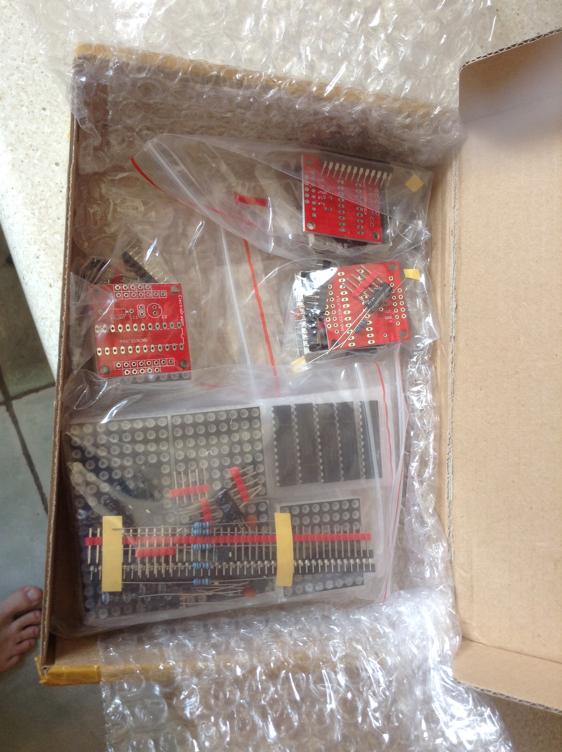
You can see this simple mod in the pictures below.

The other change I wanted to make was to make the cube more easily programmable, rather than just loading in pre-set patterns, and to make the refreshing of the cube more independent of the main code.
To do the former, I added a few functions to set and clear the appropriate bits in an array that I can simply load into the cube when convenient.
unsigned int display[4];

void setpixel (int x, int y, int z) {
  // z defines the plane
  // within the plane, x + y*4 defines the bit
  display[z] = display[z] | (1<<(x+y*4));
}

void clrpixel (int x, int y, int z) {
  display[z] = display[z] & (~(1<<(x+y*4)));
}

void clrdisplay () {
  display[0] = 0;
  display[1] = 0;
  display[2] = 0;
  display[3] = 0;
}
To improve the scanning of the cube, I decided to use the hardware timer interrupt available on timer 1 in the arduino. After initially thinking about setting the registers directly, I decided the TimerOne library is actually so simple to use, I may as well just use that – so I did.
To initialise the timer:
// Use Timer1 on the Ardunio to trigger the update scan in the background
Timer1.initialize(1000);
Timer1.attachInterrupt (ics444_display_scan);
And the scan routine looks like this:
int ics444_scan_count=0;
void ics444_display_scan () {
  if (ics444_scan_count == 0) {
    digitalWrite(LED_Plane[0], HIGH);
    digitalWrite(LED_Plane[1], HIGH);
    digitalWrite(LED_Plane[2], HIGH);
    digitalWrite(LED_Plane[3], HIGH);
    write_74HC595 (HC595_display[0]);
    digitalWrite(LED_Plane[0], LOW);
    ics444_scan_count++;
  }
  else if (ics444_scan_count == 1) {
    digitalWrite(LED_Plane[0], HIGH);
    digitalWrite(LED_Plane[1], HIGH);
    digitalWrite(LED_Plane[2], HIGH);
    digitalWrite(LED_Plane[3], HIGH);
    write_74HC595 (HC595_display[1]);
    digitalWrite(LED_Plane[1], LOW);
    ics444_scan_count++;
  }
  else if (ics444_scan_count == 2) {
    digitalWrite(LED_Plane[0], HIGH);
    digitalWrite(LED_Plane[1], HIGH);
    digitalWrite(LED_Plane[2], HIGH);
    digitalWrite(LED_Plane[3], HIGH);
    write_74HC595 (HC595_display[2]);
    digitalWrite(LED_Plane[2], LOW);
    ics444_scan_count++;
  }
  else {
    digitalWrite(LED_Plane[0], HIGH);
    digitalWrite(LED_Plane[1], HIGH);
    digitalWrite(LED_Plane[2], HIGH);
    digitalWrite(LED_Plane[3], HIGH);
    write_74HC595 (HC595_display[3]);
    digitalWrite(LED_Plane[3], LOW);
    ics444_scan_count = 0;
  }
}
Note that for each tick of the timer I display one plane then move onto the next one for the next tick. Initially I had it setting each plane in sequence, but then found I needed a short delay between each plane to actually allow the LEDs to illuminate without bleeding into each other, hence splitting it up. I also found that if I don’t pre-set all four planes to HIGH (i.e. turning them off) before selecting the pattern I wanted, I’d also get some bleeding of values across planes, hence the sequence: a) turn all planes off; write the 16 bits to the plane as data; turn on the plane to be illuminated; wait before doing the next plane.
This seems to create a nice scanning persistence of vision effect without having to worry about when to trigger the scanning from the main code. The last bits of glue are something to update a buffer containing the pattern to display (stored in LED_Plane[0-3] in the above code) and pretty much the same code as before for the actual writing to the registers of the 74HC595.
One gotcha – I set all my icstation4x4x4 code into a separate cpp and header file, so when I tried to #include <TimeOne.h> in my .cpp file, I kept getting:
icstation4x4x4.cpp:1:22: fatal error: TimerOne.h: No such file or directory
 #include <TimerOne.h>
Which was starting to drive me crazy as I could see the library was installed correctly, etc. After some Googling, eventually searching for “Arduino use of libraries from other libraries” or something like that, I found out that the compiler won’t include paths to libraries unless they are included in the main sketch file. Consequently to use <TimerOne.h> in my .cpp I also need to #include <TimerOne.h> in my main sketch file too. A quirk of the “C++ but not quite C++” nature of the Arduino IDE I guess.
Full code for my icstation4x4x4 included below. Note: This is not written to be particularly good code (I don’t use portable definitions for 16-bit values, and there is minimal error checking, etc – this is just my hacking about, not meant for real use anywhere – I might tidy I up one day – maybe). If you want to do it all properly, I suggest you take a look at the rather fine library described here: https://arduinoplusplus.wordpress.com/2015/08/13/device-independent-control-for-led-cubes/
Kevin.
Main Sketch:
#include <TimerOne.h>
#include "icstation4x4x4.h"

unsigned int display[4];

void setpixel (int x, int y, int z) {
  // z defines the plane
  // within the plane, x + y*4 defines the bit
  display[z] = display[z] | (1<<(x+y*4));
}

void clrpixel (int x, int y, int z) {
  display[z] = display[z] & (~(1<<(x+y*4)));
}

void clrdisplay () {
  display[0] = 0;
  display[1] = 0;
  display[2] = 0;
  display[3] = 0;
}

void setup() {
  // put your setup code here, to run once:
  ics444_setup();
}

int x=0;
int y=0;
int z=0;
void loop() {
  // put your main code here, to run repeatedly:
  clrdisplay();
  int i;
  for (i=0; i<32; i++)
  {
    setpixel (random(4), random(4), random(4));
  }
  ics444_display(&display[0]);
  delay (2000);
}
icstation4x4x4.cpp:
#include <TimerOne.h>
#include "icstation4x4x4.h"
// Note: Original shield was wired to use pins 0-7, plus GND and +5V.
// This has been re-wired to use pins 9 and 10 instead of 0 and 1
// in order to free up 0/1 (RX/TX) for use as a serial port and 8 for use
// with the Ciseco SRF radios (0/1 is the serial connection to the
// radio and 8 is the radio 'enable' pin).
//
int HC595_clockPin=9; // SH_CP of 74HC595
int HC595_latchPin=10; // ST_CP of 74HC595
int HC595_dataPin=3; // DS of 74HC595
int HC595_enablePin=2; // Not OE of 74HC595
int LED_Pin16= 4;
int LED_Pin17= 5;
int LED_Pin18= 6;
int LED_Pin19= 7;
int LED_Plane[] = {LED_Pin16, LED_Pin17, LED_Pin18, LED_Pin19};
unsigned int HC595_display[4];
// Each line (8 bytes) is an entire cube, with two consecutive bytes per plane of LEDS,
// and 16 LEDS per plane. LEDs are encoded in the following order:
// Lowest plane byte 1, lowest plane byte 2, second lowest plane 1, then 2,
// second from top plane 1, then 2, highest plane 1, highest plane 2.
//
// Each plane is encoded looking at the Arduino oriented with the USB/power
// designated by 'south' by started 'north west' as follows:
// D0 D1 D2 D3
// D4 D5 D6 D7
// D8 D9 D10 D11
// D12 D13 D14 D15
//
// D16 D17 D18 D19
// (USB) (Power)
// With D16 being the lowest plane, through to D19 being the highest plane
// Of course, if you wire the planes up differently, that is up to you!
//
// Each two bytes of the pattern are therefore:
// B00000000, B00000000 -> D0-7, D8-15
// with D0 = msb of the first value, D7 being the lsb of the first value,
// and D8 = msb of the second value, D15 being the lsb of the second value.
//
// So the entire pattern is:
// B10010000,B00001001,B00000000,B00000000,B00000000,B00000000,B10010000,B00001001,
// | | | || | | | ||
// | | | |\ D15 bottom plane | | | |\ D15 top plane
// | | | \ D14 bottom plane | | | \ D14 top plane
// | | \ D8 bottom plane | | \ D8 top plane
// | \ D7 bottom plane | \ D7 top plane
// \ D0 bottom plane \ D0 top plane
//
// Comment following in or out to switch patterns in or out
//#define SWAP 1
//#define SNAKE 1
//#define BURST 1
//#define SPIRAL 1
//#define ALT 1
unsigned char pattern[] = {
B00000000,B00000000,B00000000,B00000000,B00000000,B00000000,B00000000,B00000000,
#ifdef SWAP
B10010000,B00001001,B00000000,B00000000,B00000000,B00000000,B10010000,B00001001,
B00000000,B00000000,B10010000,B00001001,B10010000,B00001001,B00000000,B00000000,
B00000000,B00000000,B01100000,B00000110,B01100000,B00000110,B00000000,B00000000,
B01100000,B00000110,B00000000,B00000000,B00000000,B00000000,B01100000,B00000110,
B00001001,B10010000,B00000000,B00000000,B00000000,B00000000,B00001001,B10010000,
B00000000,B00000000,B00001001,B10010000,B00001001,B10010000,B00000000,B00000000,
B00000000,B00000000,B00000110,B01100000,B00000110,B01100000,B00000000,B00000000,
B00000110,B01100000,B00000000,B00000000,B00000000,B00000000,B00000110,B01100000,
#endif
#ifdef SNAKE
B11001100,B00000000,B11001100,B00000000,B00000000,B00000000,B00000000,B00000000,
B00000000,B00000000,B11001100,B00000000,B11001100,B00000000,B00000000,B00000000,
B00000000,B00000000,B00000000,B00000000,B11001100,B00000000,B11001100,B00000000,
B00000000,B00000000,B00000000,B00000000,B00001100,B11000000,B00001100,B11000000,
B00000000,B00000000,B00000000,B00000000,B00000000,B11001100,B00000000,B11001100,
B00000000,B00000000,B00000000,B00000000,B00000000,B01100110,B00000000,B01100110,
B00000000,B00000000,B00000000,B00000000,B00000000,B00110011,B00000000,B00110011,
B00000000,B00000000,B00000000,B00110011,B00000000,B00110011,B00000000,B00000000,
B00000000,B00110011,B00000000,B00110011,B00000000,B00000000,B00000000,B00000000,
B00000011,B00110000,B00000011,B00110000,B00000000,B00000000,B00000000,B00000000,
B00110011,B00000000,B00110011,B00000000,B00000000,B00000000,B00000000,B00000000,
B01100110,B00000000,B01100110,B00000000,B00000000,B00000000,B00000000,B00000000,
#endif
#ifdef BURST
B00000000,B00000000,B00000110,B01100000,B00000110,B01100000,B00000000,B00000000,
B00000110,B01100000,B01101001,B10010110,B01101001,B10010110,B00000110,B01100000,
B01101001,B10010110,B10010000,B00001001,B10010000,B00001001,B01101001,B10010110,
B10010000,B00001001,B00000000,B00000000,B00000000,B00000000,B10010000,B00001001,
B00000000,B00000000,B00000000,B00000000,B00000000,B00000000,B00000000,B00000000,
#endif
#ifdef SPIRAL
B11001100,B00000000,B00000000,B00000000,B00000000,B00000000,B00000000,B00000000,
B01100110,B00000000,B00000000,B00000000,B00000000,B00000000,B00000000,B00000000,
B00110011,B00000000,B00000000,B00000000,B00000000,B00000000,B00000000,B00000000,
B00000011,B00110000,B00000000,B00000000,B00000000,B00000000,B00000000,B00000000,
B00000000,B00110011,B00000000,B00000000,B00000000,B00000000,B00000000,B00000000,
B00000000,B01100110,B00000000,B00000000,B00000000,B00000000,B00000000,B00000000,
B00000000,B11001100,B00000000,B00000000,B00000000,B00000000,B00000000,B00000000,
B00001100,B11000000,B00000000,B00000000,B00000000,B00000000,B00000000,B00000000,
B11001100,B00000000,B00000000,B00000000,B00000000,B00000000,B00000000,B00000000,
B00000000,B00000000,B11001100,B00000000,B00000000,B00000000,B00000000,B00000000,
B00000000,B00000000,B01100110,B00000000,B00000000,B00000000,B00000000,B00000000,
B00000000,B00000000,B00110011,B00000000,B00000000,B00000000,B00000000,B00000000,
B00000000,B00000000,B00000011,B00110000,B00000000,B00000000,B00000000,B00000000,
B00000000,B00000000,B00000000,B00110011,B00000000,B00000000,B00000000,B00000000,
B00000000,B00000000,B00000000,B01100110,B00000000,B00000000,B00000000,B00000000,
B00000000,B00000000,B00000000,B11001100,B00000000,B00000000,B00000000,B00000000,
B00000000,B00000000,B00001100,B11000000,B00000000,B00000000,B00000000,B00000000,
B00000000,B00000000,B11001100,B00000000,B00000000,B00000000,B00000000,B00000000,
B00000000,B00000000,B00000000,B00000000,B11001100,B00000000,B00000000,B00000000,
B00000000,B00000000,B00000000,B00000000,B01100110,B00000000,B00000000,B00000000,
B00000000,B00000000,B00000000,B00000000,B00110011,B00000000,B00000000,B00000000,
B00000000,B00000000,B00000000,B00000000,B00000011,B00110000,B00000000,B00000000,
B00000000,B00000000,B00000000,B00000000,B00000000,B00110011,B00000000,B00000000,
B00000000,B00000000,B00000000,B00000000,B00000000,B01100110,B00000000,B00000000,
B00000000,B00000000,B00000000,B00000000,B00000000,B11001100,B00000000,B00000000,
B00000000,B00000000,B00000000,B00000000,B00001100,B11000000,B00000000,B00000000,
B00000000,B00000000,B00000000,B00000000,B11001100,B00000000,B00000000,B00000000,
B00000000,B00000000,B00000000,B00000000,B00000000,B00000000,B11001100,B00000000,
B00000000,B00000000,B00000000,B00000000,B00000000,B00000000,B01100110,B00000000,
B00000000,B00000000,B00000000,B00000000,B00000000,B00000000,B00110011,B00000000,
B00000000,B00000000,B00000000,B00000000,B00000000,B00000000,B00000011,B00110000,
B00000000,B00000000,B00000000,B00000000,B00000000,B00000000,B00000000,B00110011,
B00000000,B00000000,B00000000,B00000000,B00000000,B00000000,B00000000,B01100110,
B00000000,B00000000,B00000000,B00000000,B00000000,B00000000,B00000000,B11001100,
B00000000,B00000000,B00000000,B00000000,B00000000,B00000000,B00001100,B11000000,
B00000000,B00000000,B00000000,B00000000,B00000000,B00000000,B11001100,B00000000,
#endif
#ifdef ALT
B11111001,B10011111,B10010000,B00001001,B10010000,B00001001,B11111001,B10011111,
B00000110,B01100000,B01101001,B10010110,B01101001,B10010110,B00000110,B01100000,
B00000000,B00000000,B00000110,B01100000,B00000110,B01100000,B00000000,B00000000,
B00000110,B01100000,B01101001,B10010110,B01101001,B10010110,B00000110,B01100000,
#endif
};
int patternNumber=0;
int numPatterns=sizeof(pattern)/8;
int tickCount=0;
int tickCountMax=50; // How many times to loop before changing the pattern
unsigned int currentPattern[4];
/*
Protocol for sending the data to the hc595 is as follows:
(see: http://www.arduino.cc/en/Tutorial/ShiftOut)
"when the clock pin goes from low to high, the shift register
reads the state of the data pin ... when the latch pin goes
from low to high the sent data gets moved from the shift
registers ... to the output pins"
As we have two HC595s chained together, we use a 16 bit input value
*/
void write_74HC595 (unsigned int hc595value) {
digitalWrite(HC595_latchPin, LOW); // ensures LEDs don't light whilst changing values
// digitalWrite(HC595_enablePin, HIGH); // OE is negative logic
// Shift each 8 bit value in sequence - the two chained HC595s automatically grab
// the right bits - the first 8 to the first chip, second 8 to the second chip
shiftOut(HC595_dataPin, HC595_clockPin, LSBFIRST, hc595value);
shiftOut(HC595_dataPin, HC595_clockPin, LSBFIRST, (hc595value >> 8));
digitalWrite(HC595_latchPin, HIGH); // data transferred from shift register to outputs when latch goes LOW->HIGH
// digitalWrite(HC595_enablePin, LOW); // re-enable (negative logic again)
}
/*
Inputs: Array of 4 16-bit integers - one for each plane
*/
void ics444_display (unsigned int *pPattern) {
HC595_display[0]=pPattern[0];
HC595_display[1]=pPattern[1];
HC595_display[2]=pPattern[2];
HC595_display[3]=pPattern[3];
}
int ics444_scan_count=0;
void ics444_display_scan () {
if (ics444_scan_count == 0) {
digitalWrite(LED_Plane[0], HIGH);
digitalWrite(LED_Plane[1], HIGH);
digitalWrite(LED_Plane[2], HIGH);
digitalWrite(LED_Plane[3], HIGH);
write_74HC595 (HC595_display[0]);
digitalWrite(LED_Plane[0], LOW);
ics444_scan_count++;
}
else if (ics444_scan_count == 1) {
digitalWrite(LED_Plane[0], HIGH);
digitalWrite(LED_Plane[1], HIGH);
digitalWrite(LED_Plane[2], HIGH);
digitalWrite(LED_Plane[3], HIGH);
write_74HC595 (HC595_display[1]);
digitalWrite(LED_Plane[1], LOW);
ics444_scan_count++;
}
else if (ics444_scan_count == 2) {
digitalWrite(LED_Plane[0], HIGH);
digitalWrite(LED_Plane[1], HIGH);
digitalWrite(LED_Plane[2], HIGH);
digitalWrite(LED_Plane[3], HIGH);
write_74HC595 (HC595_display[2]);
digitalWrite(LED_Plane[2], LOW);
ics444_scan_count++;
}
else {
digitalWrite(LED_Plane[0], HIGH);
digitalWrite(LED_Plane[1], HIGH);
digitalWrite(LED_Plane[2], HIGH);
digitalWrite(LED_Plane[3], HIGH);
write_74HC595 (HC595_display[3]);
digitalWrite(LED_Plane[3], LOW);
ics444_scan_count = 0;
}
}
/*
Inputs: Array of 8 8-bit integers - two for each plane
*/
void ics444_displayBytes (byte *pPattern)
{
unsigned int pattern[4];
pattern[0] = pPattern[0]*256 + pPattern[1];
pattern[1] = pPattern[2]*256 + pPattern[3];
pattern[2] = pPattern[4]*256 + pPattern[5];
pattern[3] = pPattern[6]*256 + pPattern[7];
ics444_display (&pattern[0]);
}
void ics444_setup() {
// put your setup code here, to run once:
pinMode( HC595_latchPin, OUTPUT );
pinMode( HC595_clockPin, OUTPUT );
pinMode( HC595_dataPin, OUTPUT );
pinMode( HC595_enablePin, OUTPUT );
pinMode( LED_Pin16, OUTPUT );
pinMode( LED_Pin17, OUTPUT );
pinMode( LED_Pin18, OUTPUT );
pinMode( LED_Pin19, OUTPUT );
digitalWrite(LED_Pin16,HIGH);
digitalWrite(LED_Pin17,HIGH);
digitalWrite(LED_Pin18,HIGH);
digitalWrite(LED_Pin19,HIGH);
// digitalWrite(HC595_enablePin, LOW); // Enable Not OE (negative logic)
HC595_display[0]=0;
HC595_display[1]=0;
HC595_display[2]=0;
HC595_display[3]=0;
// Use Timer1 on the Ardunio to trigger the update scan in the background
Timer1.initialize(1000);
Timer1.attachInterrupt (ics444_display_scan);
patternNumber=0;
tickCount = tickCountMax;
}
// To be called from the loop()
void ics444_demo ()
{
int i;
// only update it every tick otherwise just display as is
tickCount--;
if (tickCount <= 0)
{
tickCount = tickCountMax;
for (i=0; i<4; i++)
{
currentPattern[i] = pattern[i*2 + patternNumber*8] * 256 + pattern[i*2 + 1 + patternNumber*8];
}
patternNumber++;
if (patternNumber >= numPatterns)
{
patternNumber = 0;
}
}
ics444_display(¤tPattern[0]);
}
icstation4x4x4.h:
#ifndef ICS444_H
#define ICS444_H
#include <arduino.h>

// To be called from the setup() routine
void ics444_setup(void);

// Perform one scan of the cube to display a complete pattern
//    Inputs: Four 16 bit integers, one for each plane of the cube
//    Order: Bottom plane to top plane, D0 to D15
void ics444_display (unsigned int *pPattern);

// As above, but takes the input as eight 8 bit values instead
// that is two per plane (ordered bottom to top once again)
void ics444_displayBytes (byte *pPattern);

// Displays the built-in patterns
// To be called from the loop() routine
// NB: Need to make sure the patterns are not commented out
//        in icstation4x4x4.cpp otherwise, none will be included
void ics444_demo (void);
#endif


You must be logged in to post a comment.