I like LEDs – always have enjoyed flashing a few lights, so after playing around with various LED matrices I thought it was time to go 3D. My electronics aren’t quite up to fully going it alone, so I after some googling around, I found the icStation 4x4x4 LED cube shield for the Arduino, which seemed just the thing for me – cheap (less than $6! Yes, really!), not too difficult looking to solder, and all nicely shield-shaped to make it easy to programme.
Unfortunately, whilst now it is all up and running, and the shield is great, I was really struggling with the provided build instructions and sample code. By way of example, the instructions document is called the ‘welding guide’ rather than soldering – so you get the idea, it has been translated over to English, which means there is not a little head-scratching before you are actually able to proceed. With that in mind, I thought I’d make a few notes here in case anyone else has one of these and too is trying to work out quite what the thinking behind it was!
The shield is based around the 75HC595 shift register – so if you want to know the general principles, there are a number of tutorials around – I suggest reading this generic Arduino ShiftOut Tutorial to get the hang of the basics. The basic circuit is relatively straight forward once you’ve spotted how it works. In a nutshell, the main principles are as follows:
- The 74HC595 provides a means to connect 8 LEDs to the Arduino serial port.
- There are two 74HC595s chained together, which means you can control 16 LEDs at a time.
- The Arduino serial port is used to connect to the two 74HC595 chips, so pumping a 16-bit value down the serial port, with appropriate signalling on a couple of control lines, will set the outputs of the 74HC595.
- The outputs of the HC74595 are connected to each ‘column’ of LEDs (via their anodes).
- Four Arduino digital out pins are used to connect to each ‘plane’ of LEDs (via their cathodes).
- Loading the shift registers chooses which columns to illuminate and bringing some of the four Arduino digital pins low will select which planes of LEDs will actually light up.
- If you want different patterns on each plane of LEDs, then you have to ‘scan’ them by setting the data values, and manipulating the Arduino digital out pins accordingly.
This is all apparent if you follow the tutorials, read up a bit about the 74HC595 and follow the circuit provided in the kit. But I’m afraid to say, I didn’t get much from the example code and library provided, which seemed to me to have significant bugs in the handling of the selecting of the planes of LEDs! Consequently, I wrote my own, which I’ll provide in another post.
Building the Cube
But first, some hints on actually building the thing. The guide for constructing the main shield is fairly straight forward, so I’ll not repeat that here. I thought it was quite a neat idea to use header sockets with the plastic removed as sockets for the LED legs, but breaking the plastic housing away did often mean one of the bare sockets might ping out of my wire cutters across the room! Good job there were a few spares. Remember to put the two ICs in their sockets though before you attempt to connect up LEDs – I didn’t and nearly mangled my cube trying to insert them afterwards!
Somewhere I read that it is a good idea to test your LEDs with a 3v button cell. I know there are 64 to do, but it is very quick to test them by slipping the button cell between the two legs, observing the correct polarity of course, and checking they work, so I did this – all good.
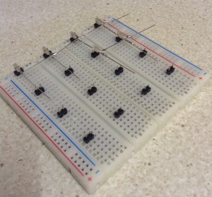
It did take me a good few minutes however to realise that the build instructions suggest making a frame to hold the LEDs whilst they are being soldered together. In fact, the design suggests that you construct a vertical slice of four columns of LEDs at a time, in order to get them nicely aligned. Extra header pin connectors are provided for this purpose, but rather than make a frame by soldering these to some stripboard, which seems to be the suggestion, I just stuck them into some breadboard as shown below.
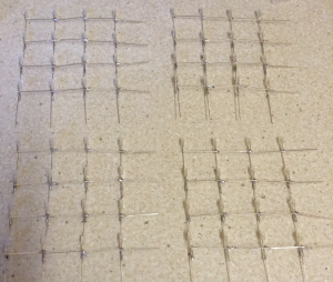
Note that I’ve used two breadboards together, after having first remove some of the power rails. I took the advice of the ‘welding guide’ and placed the header pins 2cm apart and am placing the LEDs side-on, so that, again as suggested in the guide, with the cathodes (shorter legs) bent at 90% as shown. I soldered them a single horizontal row at a time, by soldering the bent legs together. Then, once two rows were made, connected the vertical legs together, thus building up each vertical plane of four columns as shown in the following pictures.
The end result is a single slice through the cube consisting of 16 LEDs in a 4×4 plane as follows. You can start to see how the ‘matrix’ effect will work, as there should be four vertical connections and four horizontal connections, with an LED straddling each cross-over point. Naturally the verticals and horizontals themselves don’t touch otherwise it would short out across the LED.
Now at this point, I decided to test them all again, by connecting my 3v button cell between each vertical and horizontal end point. Good job I did, as after constructing my second plane, I found one of the LEDs wasn’t working, so I unsoldered it and replaced it – thankfully the kit came with spares. Eventually I had all four vertical planes, each with 16 LEDs in a 4×4 grid, finished as follows.
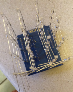
So, each of the ‘down’ legs will get plugged into one of the 16 header sockets already soldered to the shield connecting them to the data pins of the two 74HC595s. But the ‘across’ legs need to be connected together somehow to form a single conductive plane, so that each horizontal plane can then be connected to one of the four Ardunio digital out pins to complete the circuit. In order to form the horizontal planes, I bent the surplus bent LED legs over as follows:
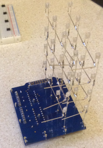
Then I could start assembling each vertical plane by inserting them into the shield, one at a time:
Note that I left the last set ‘unbent’, but the others I then soldered together to form the horizontal planes. This proved a bit tricky mind, as I ended up with three legs all coming together pretty much in the same place – so as I was attempting to solder the new horizontal in place, I was as often as not, also unsoldering the existing LED connection I had already made. There may well be a better way to do this – maybe using jumper wires across the other end of each plane instead of the spare LED legs … but anyway, I managed it eventually.
At this point, it was worth checking the connections of each plane with that 3v button cell again (although I didn’t check all 64 combinations again – just a token few in each horizontal plane). Finally, I used some jumper wires to connect each horizontal plane to one of the header sockets connected to the Arduino data pins. On the diagrams these were labelled D16 to D19. I connected the top plane to D16, then moved down for D17, D18 and connected the bottom plane to D19. There was no guidance as to which way round it should be, but as we’ll see later, due to bugs in the library it made no difference anyway! Ultimately it is down to you coding it the same way around as your wiring.
And that was construction pretty much complete. At this point you should be able to plug it into your Arduino Uno, download the sample code from icStation (really though – a rar file?) and load up the demo and you should see lights flashing and be able to spot if anything isn’t quite right.
And then things got a bit complicated – but more on that in my next post.
Kevin


Hello!
Can you show the connection to the arduino one?
Regards,
Johannes
Hi.
I’m not entirely sure I understand your question, but will try.
The Arduino connection is using the Arduino UNO shield format. If i remember correctly, it uses 8 digital output pins. 4 are used for the serial connection to the shift registers (pins 1 to 4 by default) and 4 more are used for the LED columns (5 to 8).
There is a bit more about how that maps to software, plus some pics of a mod I made to free up the UART for something else in a follow up post, see https://emalliab.wordpress.com/2015/08/18/icstation-4x4x4-led-cube-shield-for-arduino-reprise/
Does that help at all?
Kevin
Hi Kevin. Can u show the hardware please? Resistances and arduino side?
Thank u